Enerpac SafeLink User Manual
Page 4
6.0 INSTALLATION
6.1 Overview
The SafeLink wireless pressure monitoring system continuously
monitors the clamping pressure in a fi xture during the machining
process. It is designed to be interfaced to the machine control so
the machine can be stopped immediately if clamping pressure is
lost. If desired, the SafeLink system can also be used to monitor
limit switch based position sensing on clamping cylinders.
The basic SafeLink system consists of a battery powered send
unit (SLS-1, SLS-2 or SLS-3) mounted in or on the fi xture, and
a matching receive unit (SLR-1 or SLR-2) that is connected and
interfaced to the machine control. Radio communication between
the two units is 2.4 GHz.
Pressure switches (sold separately) are installed in each fi xture
circuit to be monitored. Loss of pressure in one or more of the
switches is communicated from the send unit to the receive unit,
resulting in a fault condition being triggered. The machine control
will then initiate appropriate shut down of the machinery.
A special communication verifying feature in the receive unit
periodically queries the send unit every few seconds, to ensure
that it is responding. If there is no response, a fault condition
will be triggered, and the machine control will initiate appropriate
shut down of the machinery.
Up to 47 send units can be linked to one receive unit if
Modbus
TCP/IP or Ethernet IP
communication protocol is used. These
protocols require the use of the SafeLink SLEB-1 Ethernet Bridge.
IMPORTANT: Installation and setup instructions are contained
in the following sections of this manual. These instructions are
intended only for use by experienced installation technicians with
appropriate skills and training. If custom installation services are
required, contact Enerpac for additional information.
6.2 Installing the SLR-1 or SLR-2 Receive Unit
The SLR-1 or SLR-2 receive unit should be mounted on an
external surface on the machine control enclosure, or inside of
the control enclosure on a DIN Rail using the Enerpac SLDB-1
DIN rail mounting bracket (optional accessory). See Figure 3.
Figure 3, SLDB-1 DIN Rail Mounting Bracket (optional)
The SLR-1 and SLR-2 receive units require a connection to a 24
VDC power supply. A connection of the output from the SLR-1
or SLR-2 into the machine control is also required.
Note: The SLR receive units communicate to the machine
control via either a 24 VDC output or via Modbus RTU RS485
protocol. If Modbus TCP/IP or Ethernet IP protocols are used,
the optional SLEB-1 Ethernet Bridge is required. See sections 9
and 10 of this manual for additional information.
Both models contain an external antenna jack and separate
antenna. The antenna can be cabled if the control enclosure has
a cover. Use the Enerpac SLS-2AC cable (optional accessory)
to connect either SLR receive unit to an externally mounted
antenna.
6.3 Installing the SLS-1 Send Unit on a Fixture
The SLS-1 send unit must be mounted externally on the fi xture
in a location that does not expose the unit to excessive coolant
fl ow or fl ying chips.
It must be positioned so that the internal antenna can transmit
freely without interference. Use the four 5 mm mounting holes on
the base to securely mount the unit.
The SLS-1 is IEC rated at IP67, protected from dust and
immersion to 1 meter.
6.4 Installing the SLS-2 or SLS-3 Send Unit
on a Fixture
The SLS-2 and SLS-3 send units are intended to be mounted
inside of a fi xture (such as a four-sided tombstone) in a location
that does not expose the unit to excessive coolant fl ow or fl ying
chips. The SLS-2 and SLS-3 are IEC rated at IP67, protected
from dust and immersion to 1 meter. Use the four 5 mm mounting
holes on the base to securely mount the unit.
Both models contain an external antenna jack and separate
antenna. The antenna can be cabled if the fi xture has a cover.
Use the Enerpac SLS-2AC cable (optional accessory) to connect
either SLS send unit to an externally mounted antenna.
7.0 WIRING AND CONNECTIONS
7.1 Pressure Switch Installation and Wiring
All pressure switches should be located in a protected area,
where they are not exposed to excessive coolant fl ow or fl ying
chips. Wire each switch normally open, so that the circuit in the
pressure switch will close when the pressure setting is reached,
but will go open if the system pressure has decreased below
acceptable limits.
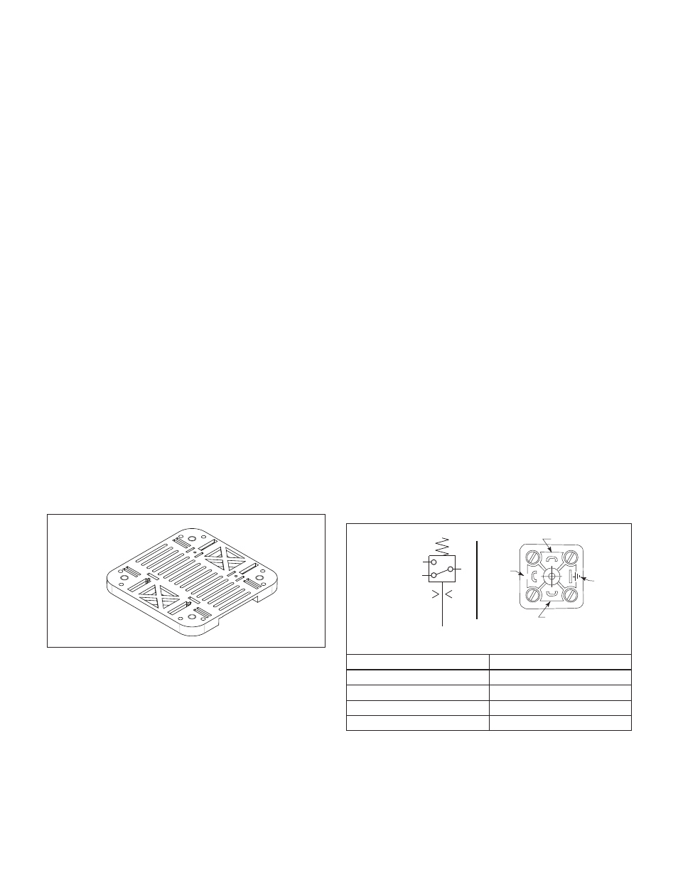
The use of an Enerpac PSCK-8 or PSCK-9 pressure switch
(optional accessory) is recommended. Connect wires to
terminals 1 and 3, so that the switch is wired normally open. See
Figure 4 for switch wiring details. Refer to Enerpac instruction
sheet L2391 for additional information regarding PSCK pressure
switch installation.
3
2
1
3
1
3
2
1
4
2
DIN Style connector plug
(with protective cover removed)
PSCK-8, PSCK-9
Wiring Diagram
Function
Terminal
Common
1
Normally Closed
2
Normally Open
3
Ground (not used)
4
Figure 4, Pressure Switch Connections (typical)
7.2 Wiring Pressure Switch to the Send Unit
(SLS-1, SLS-2 or SLS-3)
Connect the pressure switch to the SLS send unit as described
in the following procedure:
4