Machine contr oller – Enerpac SafeLink User Manual
Page 10
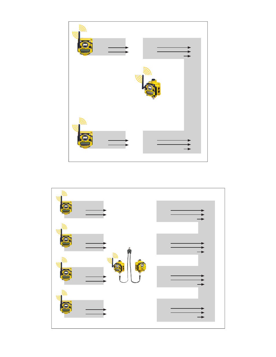
10.0 TYPICAL SYSTEM LAYOUTS
Figure 18, Basic System with I/O Machine Interface
(SLS-1 or SLS-2 with SLR-1)
machine contr
oller
Output t
o
machine contr
oller: 24 VDC fr
om RECEIVE unit.
SLR-1
“RECEIVE”
unit
SLS-1 or SLS-2
“SEND” unit
PALLET #1
Input #1
Input #2
SLS-1 or SLS-2
“SEND” unit
PALLET #2
Input #1
Input #2
PALLET #1
Input #1
Input #2
SEND/RECEIVE connected
PALLET #2
Input #1
Input #2
SEND/RECEIVE connected
Output t
o
machine contr
oller: 24 VDC fr
om RECEIVE unit and EXP
ANSION
MODULE.
SLS-1 or SLS-2
“SEND” unit
machine contr
oller
SLS-1 or SLS-2
“SEND” unit
PALLET #1
Input #1
Input #2
SLS-1 or SLS-2
“SEND” unit
PALLET #2
Input #1
Input #2
SLS-1 or SLS-2
“SEND” unit
PALLET #3
Input #1
Input #2
PALLET #4
Input #1
Input #2
PALLET #1
Input #1
Input #2
SEND/RECEIVE connected
PALLET #2
Input #1
Input #2
SEND/RECEIVE connected
PALLET #3
Input #1
Input #2
SEND/RECEIVE connected
PALLET #4
Input #1
Input #2
SEND/RECEIVE connected
SLR-1
“RECEIVE”
unit
SLEM-1
“EXPANSION
MODULE”
SLCS-1
“SPLITTER
CABLE”
Figure 19, Larger System with I/O Machine Interface (SLS-1 or SLS-2 with SLR-1)
10