Main and auxiliary feedback combinations – ElmoMC ExtrIQ Digital Servo Drives-Panther User Manual
Page 47
Panther Installation Guide
Installation
MAN-PANIG (Ver. 1.302)
47
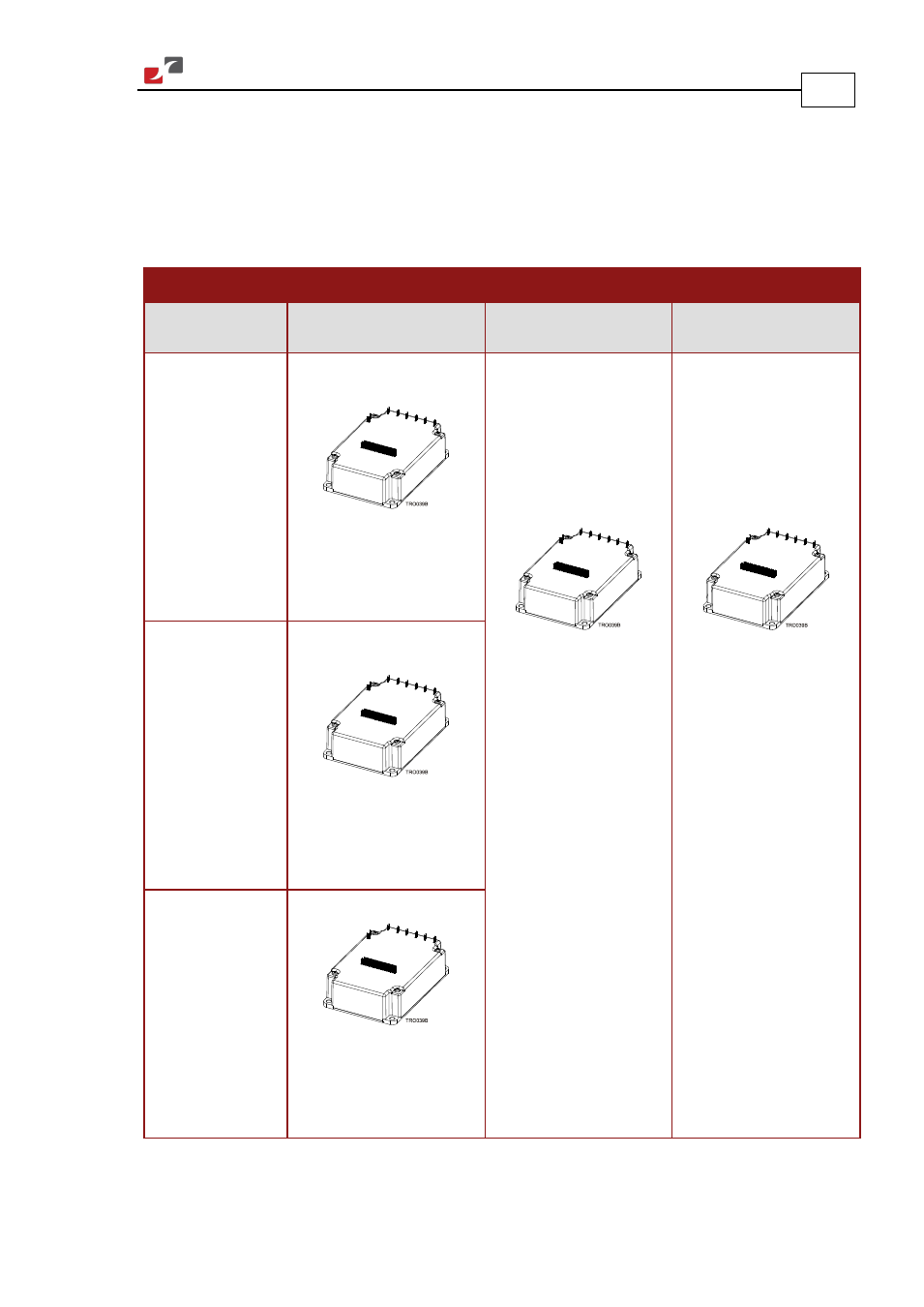
3.10.1. Main and Auxiliary Feedback Combinations
The Main Feedback is always used in motion control devices, whereas Auxiliary Feedback is
often, but not always used. The Auxiliary Feedback connector on the Panther has three bi-
directional pins (CHA, CHB and INDEX). When used in combination with Main Feedback, the
Auxiliary Feedback can be set, by software, as follows:
Main Feedback Auxiliary Feedback
Software
Setting
YA[4] = 4
(Aux. Feedback: output)
YA[4] = 2
(Aux. Feedback: input)
YA[4] = 0
(Aux. Feedback: input)
Incremental
Encoder Input
Main Feedback:
Incremental Encoder
Aux. Feedback:
There is no Aux. Feedback
output option, when an
Incremental Encoder is the
main feedback device.
Main Feedback Input:
Incremental Encoder
or Analog Encoder
or Resolver
or Absolute encoder
or Tachometer
or Potentiometer
Aux. Feedback:
Single-ended Incremental
Encoder Input
Main Feedback Input:
Incremental Encoder
or Analog Encoder
or Resolver
or Absolute encoder
or Tachometer
or Potentiometer
Aux. Feedback:
Single-ended Pulse and
Direction Commands
Interpolated
Analog
(Sine/Cosine)
Encoder Input
1. Main Feedback:
Analog Encoder
Aux. Feedback:
Analog Encoder position data,
emulated in single-ended,
un-buffered incremental
Encoder format
Resolver Input
2. Main Feedback: Resolver
Aux. Feedback:
Resolver position data
emulated in single-ended un-
buffered Incremental Encoder
format