Main power and motor power, Connecting motor power – ElmoMC ExtrIQ Digital Servo Drives-Panther User Manual
Page 29
Panther Installation Guide
Installation
MAN-PANIG (Ver. 1.302)
29
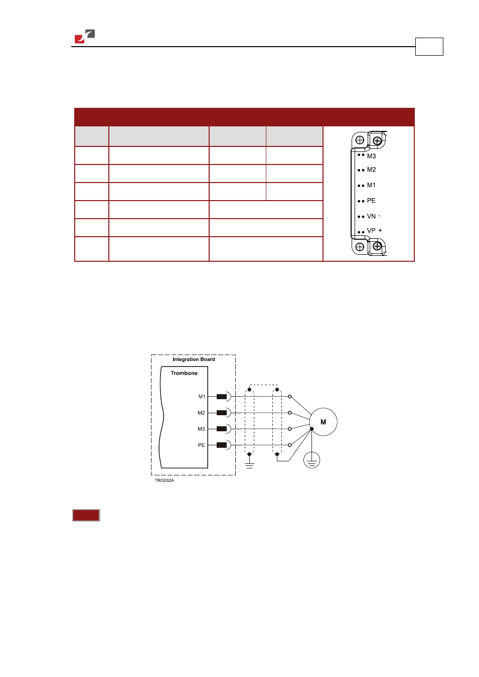
3.7. Main Power and Motor Power
The Panther receives power from main supply and delivers power to the motor. The table
below describes the pinout connections to the main power and motor power cables.
Pin
Function
Cable
Pin Positions
AC Motor
DC Motor
M3
Motor phase
Motor
Motor
M2
Motor phase
Motor
Motor
M1
Motor phase
Motor
N/C
PE
Protective Earth
Power and Motor
VN-
DC Negative Power input Power
VP+
DC Positive Power input
Power
3.7.1.
Connecting Motor Power
Connect the M1, M2, M3 and PE pins (Figure 5) on the Panther in the manner described in
section 3.5 Integrating the Panther on a PCB. The phase connection is arbitrary, as the
Composer will establish the proper commutation automatically during setup. When tuning a
number of drives, you can copy the setup file to the other drives and thus avoid tuning each
drive separately. In this case, the motor-phase order must be the same as on the first drive.
Figure 5: Motor Power Connection Diagram
Notes:
•
For best immunity, it is highly recommended to use a 4-wire shielded (not twisted) cable
for the motor connection. The gauge is determined by the actual current consumption of
the motor.
•
Connect the cable shield to the closest ground connection at the motor end.
•
Connect the cable shield to the closest PE terminal of the Panther.
•
Ensure that the motor chassis is properly grounded.