Integrating the panther on a pcb, Traces – ElmoMC ExtrIQ Digital Servo Drives-Panther User Manual
Page 24
Panther Installation Guide
Installation
MAN-PANIG (Ver. 1.302)
24
3.5. Integrating the Panther on a PCB
The Panther is designed to be mounted on a PCB, by soldering its pins directly to the PCB. The
following procedures apply.
3.5.1.
Traces
To implement Traces
1.
The size of the traces on the PCB (thickness and width) is determined by the current
carrying capacity required by the application.
The rated continuous current limit (Ic) of the Panther is the current used for sizing the
motor traces (M1, M2, M3 and PE) and power traces (VP+, VN- and PE).
For control, feedbacks and I/O conductors the actual current is very small, but
“generous” thickness and width of the conductors will contribute to better
performance and lower interference.
2.
The traces should be as short as possible to minimize EMI and to minimize the heat
generated by the conductors.
3.
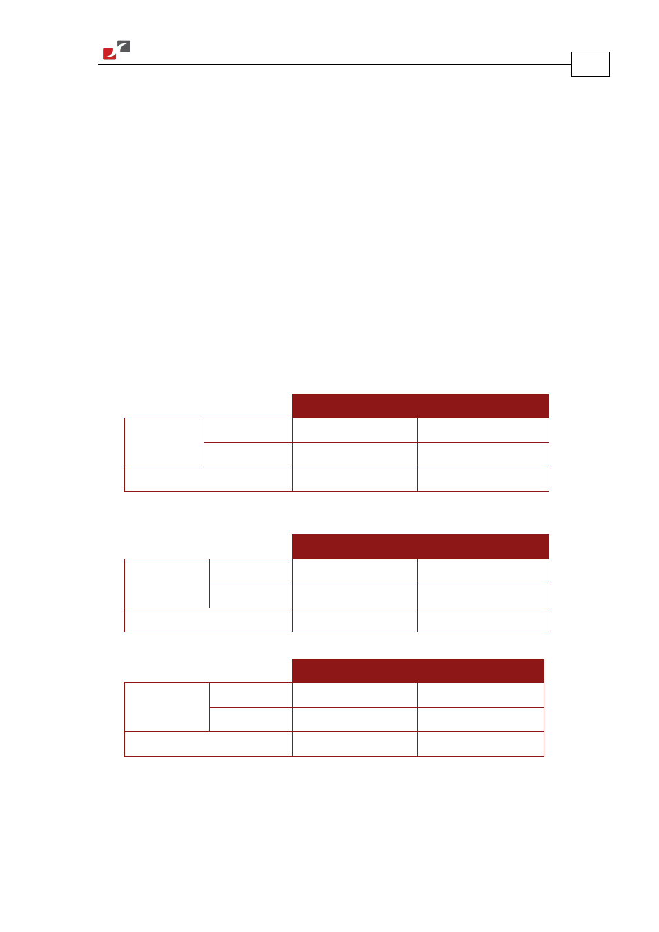
The spacing between the high voltage conductors (VP+, VN-, M1, M2, M3) must be at least:
400 V Drives
700 & 800 V Drives
Surface layer Non-coated
2.4 mm
4.2 mm
Coated
1.0 mm
2.4 mm
Internal layer
0.5 mm
1.0 mm
4.
The spacing between the high voltage conductors (VP+, VN-, M1, M2, M3) and the logic
part of the drive must be at least:
400 V Drives
700 & 800 V Drives
Surface layer
Non-coated
4.8 mm
8.4 mm
Coated
2.0 mm
3.8 mm
Internal layer
0.5 mm
1.0 mm
5.
The spacing between any voltage conductors and the PE part of the drive, must be at least:
400 V Drives
700 & 800 V Drives
Surface layer
Non-coated
2.4 mm
4.2 mm
Coated
1.0 mm
2.4 mm
Internal layer
0.5 mm
1.0 mm
Complying with the rules above will help satisfy UL safety standards, MIL-STD-275 and the
IPC-D-275 standard for non-coated conductors, operating at voltages lower than 800 VDC.