Creating a segment (command code ws) – Despatch Protocol 3 Modbus Communications User Manual
Page 40
A
DDRESS LIST
Modbus Programming Manual
40
Version 2
Copyright © 2012 by Despatch Industries.
All rights reserved. No part of the contents of this manual may be reproduced, copied or transmitted in any form or by any
means including graphic, electronic, or mechanical methods or photocopying, recording, or information storage and
retrieval systems without the written permission of Despatch Industries, unless for purchaser's personal use.
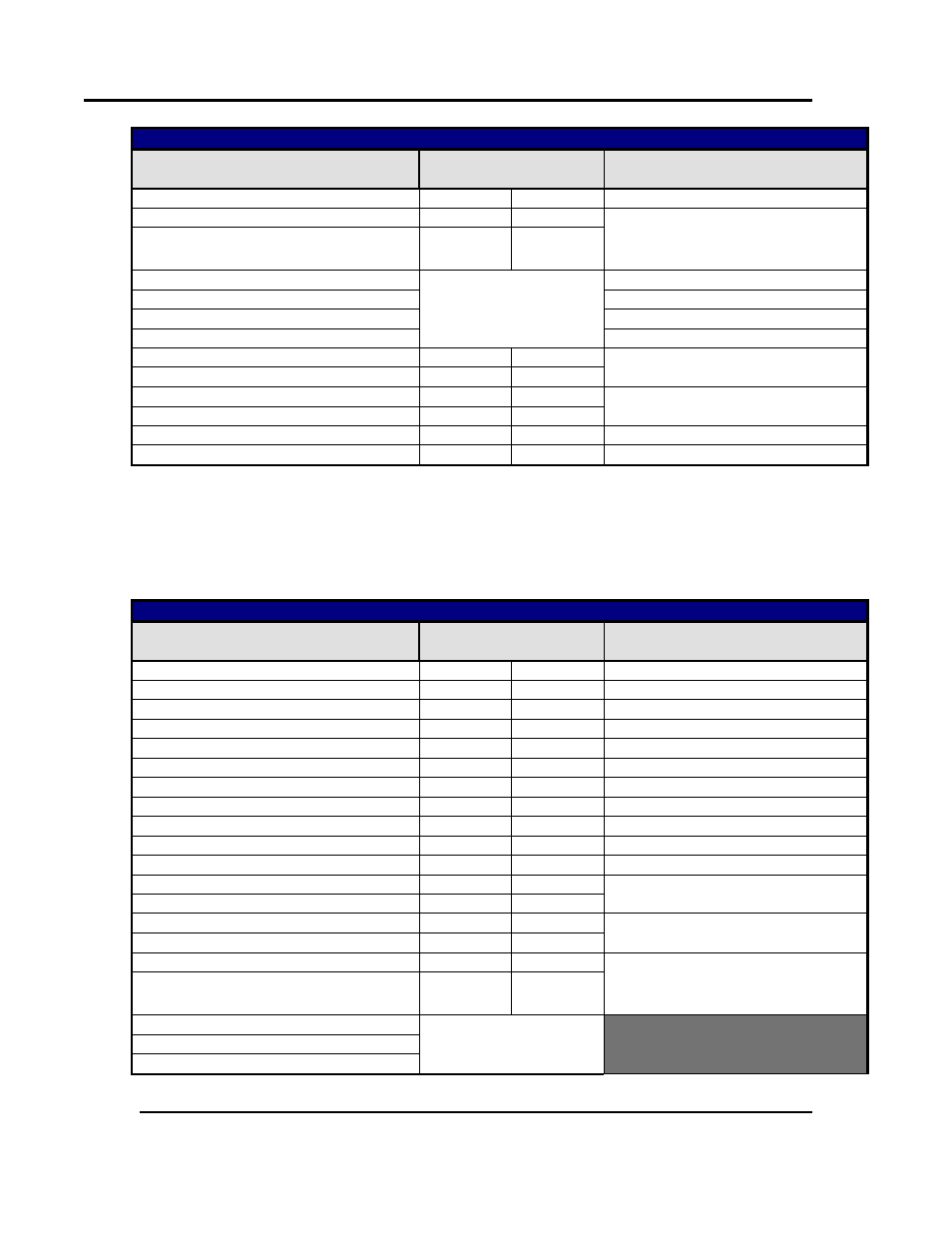
Creating Or Editing A Profile Header at a specific location - Request (to instrument)
Field Name
Data
Comments
(Dec)
(Hex)
Profile Starting Setpoint Low
01
01
Profile Recovery High Byte
00
00
0 = Control to off, 1 = Restart profile,
2 = Maintain last profile setpoint,
4 = Continue profile from where it was when
power failed
Profile Recovery Low Byte
A/R
A/R
Profile Recovery Time (Byte 4 - high)
Floating point number
Profile Recovery Time (Byte 3)
Profile Recovery Time (Byte 2)
Profile Recovery Time (Byte 1 - Low)
Profile Abort action High Byte
00
00
0 = Control to off
1 = Maintain last profile setpoint
Profile Abort Action Low Byte
A/R
A/R
Profile Cycles High Byte
A/R
A/R
1 to 9999 or 10,000 for “Infinite”
Profile Cycles Low Byte
A/R
A/R
CRC High Byte
A/R
A/R
CRC Low Byte
A/R
A/R
The instrument replies to this message with an Edit Response Message Section 2.9.5.9.
2.9.5.3. Creating a Segment (Command Code WS)
Creating new segments is only possible when a new profile is being created (see above for
instruction for creating a profile at the next available position, or at a position that you specify).
An error is returned if the correct sequence is not followed.
Creating Segments - Request (to instrument)
Field Name
Data
Comments
(Dec)
(Hex)
Unit Address
A/R
A/R
The ID address of the instrument.
Function Code
23
17
Requires the multi read/write function.
Read Start Address High Byte
32
20
Read Start Address Low Byte
06
06
Read Quantity Of Registers High
00
00
Read Quantity Of Registers Low
01
01
Write Start Address High
32
20
Write Start Address Low
06
06
Write Quantity Of Registers High
00
00
Write Quantity Of Registers Low
11
0B
Create Segment (WS) = 11dec / 0x0Bhex
Byte Count
22
16
Create Segment (WS) = 22dec / 0x16hex
Command Code High Byte
87
57
Create Segment (WS) = 22355dec /
0x5753hex
Command Code Low Byte
83
53
Profile Number High Byte
A/R
A/R
The profile number can be anything between
0 and 64
Profile Number Low Byte
A/R
A/R
Segment Type High Byte
00
00
0 = Ramp Time, 1 = Ramp Rate,
2 = Step, 3 = Dwell, 4 = Hold, 5 = Loop
6 = Join, 7 = End, 8 = Repeat sequence
then end
Segment Type Low Byte
A/R
A/R
Segment Info A (Byte 4 - High)
Floating point number
The meaning of the data contained in
Segment Info A depends on the type of
segment it relates to. See section 12.5.5.
Segment Info A (Byte 3)
Segment Info A (Byte 2)