Alarm parameters, Alarm 1, Alarm 2 – Despatch Protocol 3 Modbus Communications User Manual
Page 24
A
BOUT
T
HIS
M
ANUAL
Modbus Programming Manual
24
Version 2
Copyright © 2012 by Despatch Industries.
All rights reserved. No part of the contents of this manual may be reproduced, copied or transmitted in any form or by any means
including graphic, electronic, or mechanical methods or photocopying, recording, or information storage and retrieval systems without
the written permission of Despatch Industries, unless for purchaser's personal use.
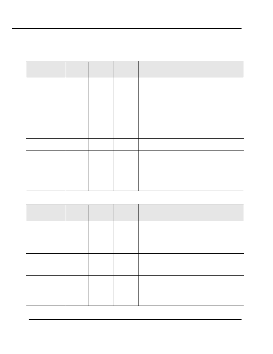
2.5. Alarm Parameters
2.5.1. Alarm 1
Parameter Name
Modbus
Address
(Dec)
Modbus
Address
(Hex)
Access
R/W
Notes
Alarm Type
6144
0x1800
R/W
0 = High Alarm
1 = Low Alarm
2 = Deviation Alarm
3 = Band Alarm
4 = Loop Alarm
5 = Sensor Break Alarm
Alarm Value
6145
0x1801
R/W
Limited by the input range maximum and minimum
for Alarm types 0 and 1. Limited by the span of the
input range for alarm types 2 and 3. Not used for
alarms 4 and 5.
Alarm Hysteresis
6146
0x1802
R/W
Limited by the span of the input range
Alarm inhibit
6147
0x1803
R/W
0 = Disabled
1 = Enabled
Alarm status
6148
0x1804
R
0 = Inactive
1 = Active
Alarm inhibit
status
6149
0x1805
R
0 = Not inhibited
1 = Inhibited
Rate Minimum
Time Alarm
Value
6150
0x1806
R/W
2.5.2. Alarm 2
Parameter Name
Modbus
Address
(Dec)
Modbus
Address
(Hex)
Access
R/W
Notes
Alarm Type
6160
0x1810
R/W
0 = High Alarm
1 = Low Alarm
2 = Deviation Alarm
3 = Band Alarm
4 = Loop Alarm
5 = Sensor Break Alarm
Alarm Value
6161
0x1811
R/W
Limited by the input range maximum and minimum
for Alarm types 0 and 1. Limited by the span of the
input range for alarm types 2 and 3. Not used for
alarms 4 and 5.
Alarm Hysteresis
6162
0x1812
R/W
Limited by the span of the input range
Alarm inhibit
6163
0x1813
R/W
0 = Disabled
1 = Enabled
Alarm status
6164
0x1814
R
0 = Inactive
1 = Active