5 tune – menu – Dakota Ultrasonics CMX DL plus User Manual
Page 32
Dakota Ultrasonics
28
VIEW: (color version only) – Provides the user with 12 different color schemes to
select from. There are two schemes for each main color option. Refer to page 117
for further info.
DIM: (color version only) – Allows the user to conserve battery life by diming the
display after idle for a specific amount of time – OFF, 30, 60, 90, 120 seconds. Once
dimmed, a single press of any key will restore the screen brightness. Refer to page
118 for further info.
RECT WAVE: This option provides the user an outlined or filled view option when
the display setting is in RECT (rectified) wave mode only. Refer to page 123 for
further info.
DETECT MARK: Selectable graphics option for the point of detection on the
waveform: Line, Box, Dots, None. Offers the user a graphics preference on how
they prefer to view the detection on the waveform.
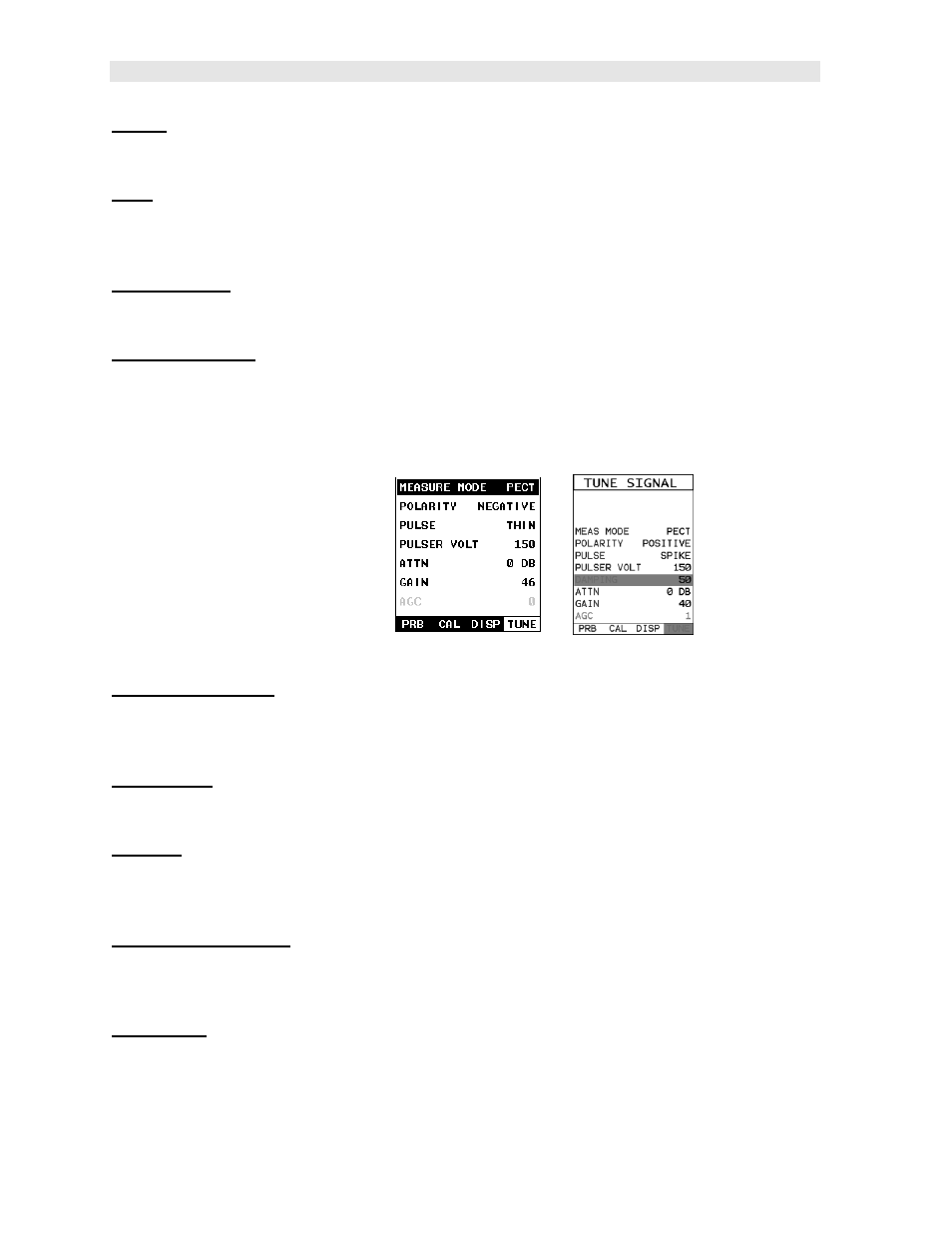
3.5 TUNE – Menu
MEASURE MODE: Toggles a variety of unique measurement modes for different
application requirements: Coating Off (P -E), Coating On (PECT), Temp Comp
(PETP), Thru Coat (E-E), Thru Verify (E-EV), Coating Only (CT). Refer to page 37
for further info.
POLARITY: The CMX
DL+
operates on a zero crossing detection principle. This
feature toggles which stroke of the cycle the crossing detection uses, either positive
or negative. Refer to page 125 for further info.
PULSE: The CMX
DL+
has an adjustable pulse width for both high penetration and
resolution applications. The pulse width refers to the duration of time the pulser is
on. The options are Spike, Thin , and Wide. Refer to page 127 for a further
explanation.
PULSER VOLTAGE: This feature offers a 50 volt cut/boost to the pulser. The
standard setting is 150 volts. This enables the CMX
DL+
to offer greater penetration
for difficult material types, or increased resolution on noisy materials. Refer to page
128 for a further explanation.
DAMPING: (color version only) – Provides the user with multiple input impedances
to match the impedance of the transducer, and optimized overall transducer
performance. Refer to page 119 for further info.