Condux CableGlider FO Cable Puller User Manual
Page 8
8
!wARNINg: Escaping fluids under pressure can penetrate the skin and cause seri-
ous personal injury. Observe the following precautions to avoid hydraulic hazards:
• Tighten all connections before applying pressure. Relieve pressure before
connecting or disconnecting hoses.
• Check for leaks with a piece of cardboard. Do not use hands!
• Do not exceed working pressure of hydraulic hoses. Visually inspect hoses
regularly and replace if damaged.
5. Run the puller for approximately 1 minute to remove any trapped air and then stop the hydraulic power
source.
!CAUTION: Use a minimum 10 micron nominal filter for proper filtration of the
hydraulic system. Equipment failure could result from improper filtration.
C. POSITION THE FOOT CONTROL vALvE ASSEmbLY
The foot control valve assembly controls the speed and direction of rotation of the
capstan. The further the foot pedal is pushed down, the faster the puller turns. To
temporarily reverse the capstan, the foot pedal can be lifted up.
!NOTE: Cable must be pulled only while pushing down on the foot pedal. To pull cable
with the capstan rotating the opposite direction, reverse the quick-connect couplings of the hydraulic hoses on
the puller (see previous section).
1. The foot control valve assembly is fitted with an adjustable speed control stop. The speed control stop
relieves operator foot fatigue by limiting the downward travel of the foot pedal. Do not force the
pedal if it does not move. Adjust the speed control knob counterclockwise to increase speed,
clockwise to decrease speed. The operator should now feel the pedal move freely.
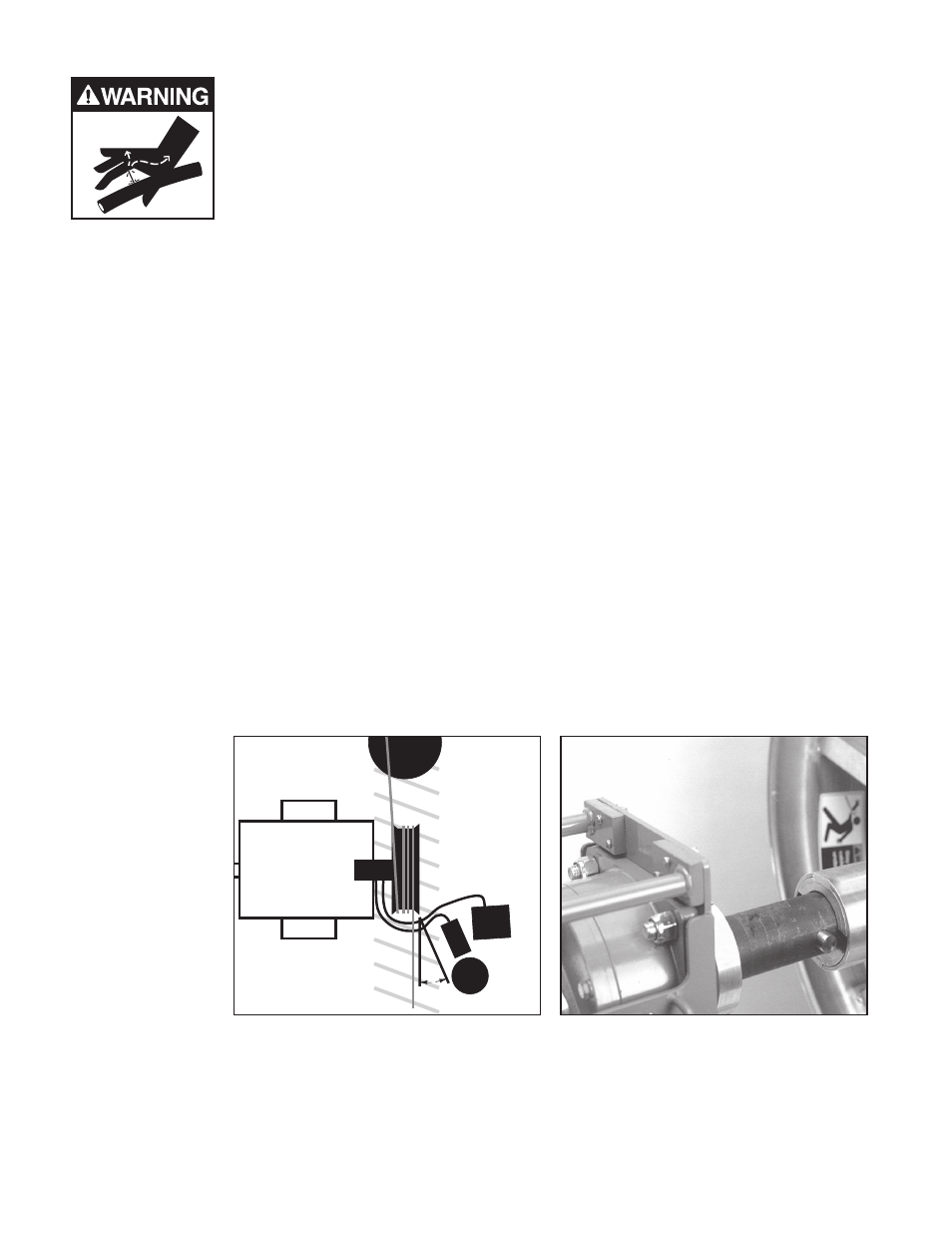
2. Position the foot control valve at least 3 to 4 feet (0.9 to 1.2 m) from the capstan’s
feed-off side (figure 3). Position the foot control in the best possible location for
safety and proper operation. Multiple operators may be required for safety or
operational requirements.
3.
The manually adjustable pressure relief valve allows a secondary method of controlling the maximum pull-
ing tension. The relief valve is factory set to release the hydraulic
pressure at approximately 700 pounds (3113 N) of pulling tension while using the Condux 30 inch (762
mm) diameter capstan. If required, adjust the relief valve to a
20°
ECB
OPERATOR
FOOT CONTROL
HAZARD AREA
Figure 3. Foot Control valve Assembly
Placement
Figure 4. Capstan Assembly