Condux CableGlider FO Cable Puller User Manual
Page 10
10
b. CONNECT THE ELECTRONICS
!DANGER: The electronic control box is an electrical device. Electric shock
hazards exist that could result in severe personal injury or death. Observe the
following precautions:
• Do not expose electronic control box to water.
• Do not remove cover of electronic control box (no user-serviceable parts inside).
Refer servicing to qualified personnel.
• The electronic control box power switch should be in the off position before
connecting or disconnecting any cords.
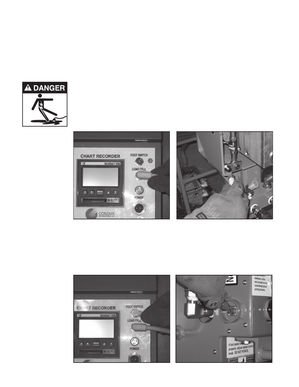
1. Connect the male end of the 5-pin sensing cord to the female connector on the Electronic Control Box
labeled “LOAD CELL”. (see Figure 6) Connect the female end of the cord to the male receptacle located
near the load cell. (See Figure 7). Before making these connections, ensure the receptacles are free of dirt
and moisture. Do not modify this cord’s length.
Tighten the connector collars over the threaded portion of the receptacles. This prevents the cord from com-
ing loose during operation. This cord is necessary to measure the tensions sensed by the load cell.
2. Connect the male end of the 3-pin footswitch control cord to the female connector on the Electronic Control Box
labeled “FOOTSWITCH” (see Figure 8). Connect the female end of the control cord to the male receptacle located
on the foot control valve assembly (see Figure 9). NOTE: If the connector on the foot switch is 2-pin, use the
patch cord (08675926) included in the upgrade kit (08675920) to convert to the required connection. Before making
these connections, ensure the receptacles are free of dirt and moisture. Do not modify this cord’s length.
Tighten the connector collars over the threaded portion of the receptacles. This prevents the cord from com-
ing loose during operation. This cord is necessary to measure the tensions sensed by the load cell.
Figure 6. Load Cell Connection on ECb
Figure 7. Load Cell Connection on Puller
Figure 8. Foot Switch Connection on ECb
Figure 9. Foot Switch Connection