Set up the puller – Condux CableGlider FO Cable Puller User Manual
Page 7
7
Set up the Puller
This manual contains setup and operating instructions for the Condux Fiber Optic Cable Puller with electronic
control box, if equipped. Where operations differ for the other available packages, the instructions specify
those differences.
A. mOUNT THE PULLER
1. The Fiber Optic Cable Puller has a 2
1
⁄
2
x 2
1
⁄
2
inch (64 x 64 mm) square mounting post. A female receiver,
such as the receivers listed in appendix 13.F and 13.G, is
recommended. Use grade 5 or grade 8 capscrews to attach these mounts. Materials used for constructing
your own mount should have a minimum wall thickness of
1
⁄
4
inch (6.25 mm). All welds should be continuous, and gussets should be used
where possible.
!CAUTION: Lift the Fiber Optic Cable Puller only with proper equipment or
sufficient manpower. Improper lifting techniques may result in personal injury
or property damage.
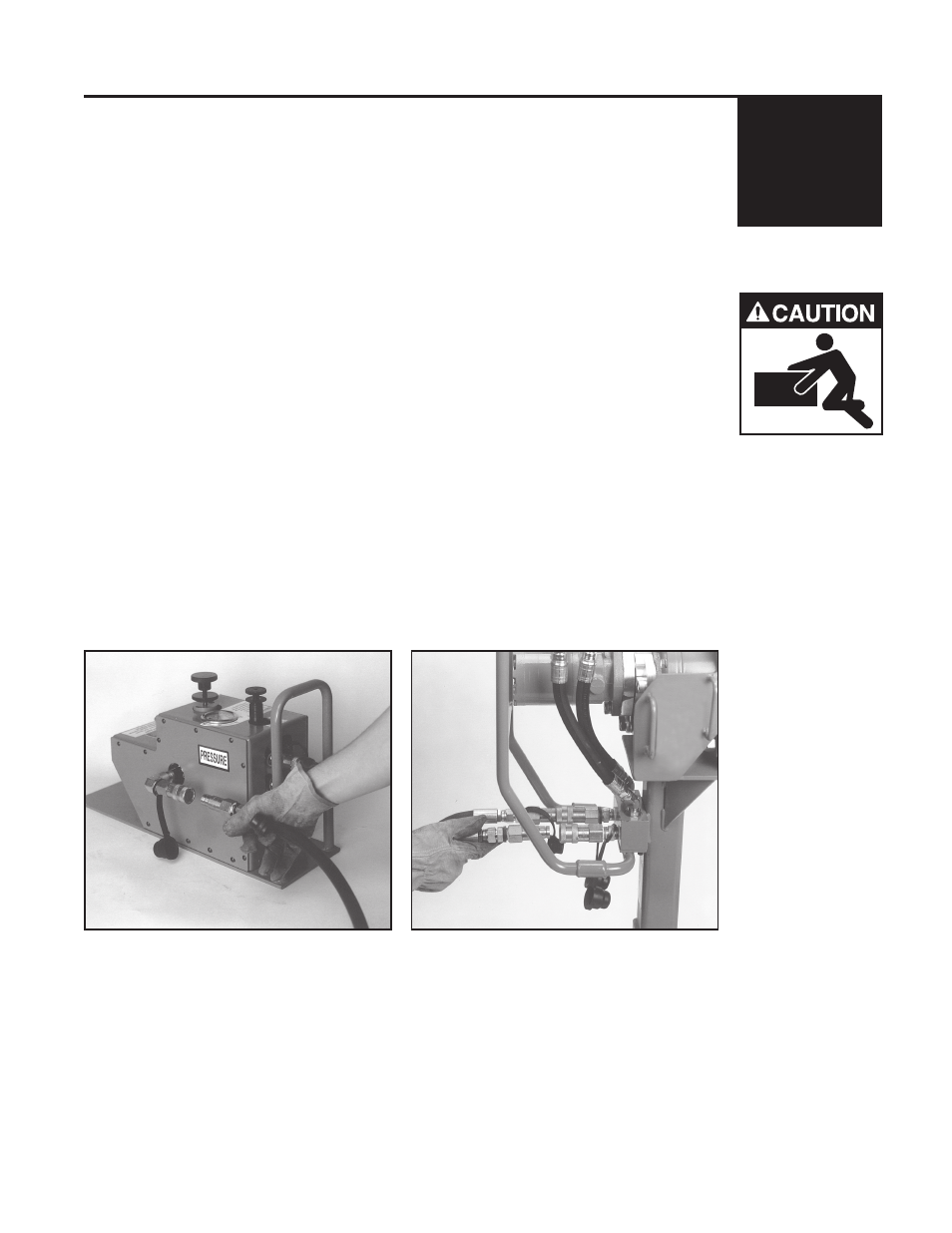
b. CONNECT THE HYDRAULIC SYSTEmS
The Fiber Optic Cable Puller’s hydraulic system uses quick-connect couplings. Keep all connections clean to
avoid contamination and possible system failure. Follow these steps to connect the hydraulic components:
1. Connect the hydraulic supply hoses to the foot control valve assembly. Ensure the pressure hose
from the power source goes to the inlet of the foot control valve (labeled PRESSURE
on the foot control valve assembly, figure 1).
2. Connect the hoses from the foot control valve assembly to the puller (figure 2). The
supply hose assembly has four identical male couplings and can be attached between the puller and foot
control valve assembly in any orientation.
!NOTE: Switching the quick-connect couplings on one end of hose assembly
between the puller and the foot control valve assembly will reverse the direction of
capstan rotation.
3. Start the hydraulic power source and check all connections for leaks with a piece of cardboard. Run the
puller in both directions to ensure proper operation.
5.
Figure 1. Power Supply Connections
Figure 2. Foot Control Connections