Condux CableGlider FO Cable Puller User Manual
Page 18
18
!CAUTION: Use the relief valve pressure only as a backup to the electronic tension
control system or other load limiting means. Damage to the cable being installed
may result.
1. Set up the puller as if cable were to be pulled, including installation of the capstan (figure 21).
2. Place a pull line around the capstan. The pull strength of the pull line must exceed the 2,000 pound maxi-
mum capacity of the Fiber Optic Cable Puller.
3. Attach the pull line to a load indicator such as a Dillion dynamometer (section 14).
4. Release the lock nut on the relief valve (figure 22). Turn the relief valve stem counterclockwise to adjust the
valve down to zero pressure.
5. Slowly apply pressure to the puller to tighten the pull line. Continue to pull until the relief valve opens. The
value shown on the dynamometer must be below the desired maximum load.
6. Release pressure to the puller. Turn the relief valve stem clockwise to increase the pressure setting (figure 22).
7. Slowly apply pressure to the puller to tighten the pull line. Continue to pull until the relief valve opens. The
value shown on the dynamometer is the maximum load that the puller can pull. Repeat steps 6 and 7 until
the desired maximum load is obtained.
8. When the desired maximum load is obtained, tighten the lock nut on the relief valve.
9. Verify the relief valve setting by slowly applying pressure until the relief valve opens. Check the value on
the dynamometer and adjust the relief valve if necessary.
!CAUTION: Use the relief valve pressure only as a backup to the electronic tension
control system or other load limiting means. Damage to the cable being installed
may result.
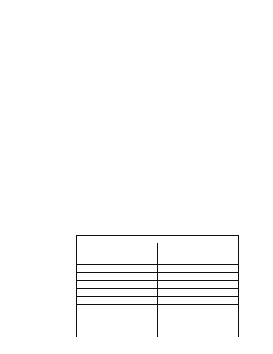
!NOTE: Measuring the hydraulic pressure to the puller is not an accurate means for determining the pulling
tensions. Component age and oil temperature affect hydraulic motor efficiency and torque output. The fol-
lowing chart shows the different approximate pulling tensions at different oil temperatures with a 30 inch (762
mm) diameter Condux capstan. Use this chart as a comparative reference only and do not
consider it to be the actual pulling tensions.
Load
(30" Capstan)
lbs. kN
Oil Temperature
42° F 6° C
106° F 41° C
160° F 71° C
Pressure
psi bar
Pressure
psi bar
Pressure
psi bar
150 0.67
750 51.7
480 33.1
500 34.5
200 0.89
800 55.2
580 40.0
550 37.9
300 1.33
975 67.2
800 55.2
725 50.0
400 1.78
1150 79.3
1000 68.9
925 63.8
500 2.22
1375 94.8
1200 82.7
1125 77.6
600 2.67
1550 106.9
1400 96.5
1325 91.4
700 3.11
1700 117.2
1600 110.3
1825 125.8
800 3.56
1900 131.0
1800 124.1
900 4.00
2050 141.3