Condux CableGlider FO Cable Puller User Manual
Page 11
11
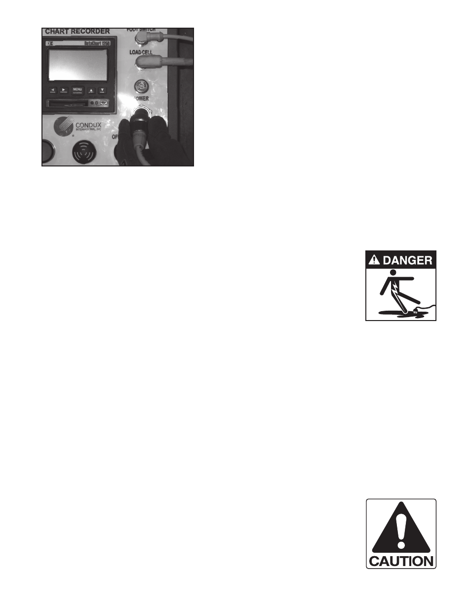
3. The 7/8” 2-pin connector on the front panel of the
electronic control box supplies electrical power to
the electronic control box. (see Figure 10) This
power can come from the power pack, a vehicles
power point, or a lighter socket. The electronic
control box requires 12 Volt DC power for proper
operation.
4. Connect the power cord to the 2-pin connector
labeled “POWER”. Before making these connec-
tions, ensure the receptacle is free of dirt and
moisture. Tighten the connector collar over the
threaded portion of the receptacle. This will pre-
vent the cord from coming loose during opera-
tion. Connect the other end of the power cord to
a 12 Volt DC power source.
C. SETTINg UP THE ELECTRONIC CONTROL bOX
The Condux Fiber Optic Tensiometer has been designed to give the operator continuous tension informa-
tion and automatic shut-off control during a pull. The Electronic Control Box features an LED Display,
Digital Graph Display, 256MB Flash Card, and a 3 capstan selection switch. A programmable overload set
point with both visual and audible alarms is designed to disengage the cable puller should an overload
occur. Navigator software is provided so pulling information can be downloaded onto any computer running
Windows 2000® or XP®.
!DANgER: The main Power switch supplies power to the indicator and chart
recorder. When a power supply is connected to the electronic control box, portions
of it are energized. Follow all electrical equipment precautions.
!NOTE: Always disconnect the power cord when the electronic control box is not in use. When the power
cord is connected to the electronic control box, it energizes portions of the control box. If the power cord is left
attached when the control box is not in use, it will drain the power supply.
1. Turn the power switch on the Electronic Control Box to the “ON” position (See Figure 5). Be sure that the
sensor cords are properly connected before turning on power.
2. Select the capstan size. Turn the capstan selection switch so the appropriate channel is lit on the
Meter. In order to get accurate results, the correct capstan size must be selected. The electronic control box
is programmed to accurately return pull tension for Condux 12”, 30”, and 42” fiber optic capstans.
3. Set the cable Tension Limit. Press the “Prog” Button and ▼ button simultaneously. (See Figure 5)
SP-1 will appear on the on the LED Screen. The screen will alternate between SP-1 and the current ten-
sion limit. Press the ▲ and▼ buttons to increase or decrease the tension limit. Once the desired tension
limit is set, press “Prog” to save the set point.
4. Zero the display. Press the “Prog” button.
5. Alarms: When Tension Limiter switch is in the “OFF” position the audio alarm will sound and the light
will come on when the tension limit is reached. When the Tension Limiter switch is in the “ON” position the
puller will also stop pulling when the tension limit is reached (See Figure 5)
!CAUTION: Damage to cable may result from excessive pulling forces. Use
precautions to safeguard against overload conditions.
D. DIgITAL CHART RECORDER SET UP
The Digital Chart Recorder is the next generation Solid State Data Recorder/Panel Recorder. This instru-
ment has all the capability of a traditional paper recorder – variable chart speeds, the ability to review his-
toric data, see trends and more. All pull data is stored on the 256MB Compact Flash Card that comes with
the unit.
1. Name File Press “MENU” button to enter the Menu screen. Use ▲ and ▼ arrows to scroll to RECORD
MODE and press menu. Next, scroll to “NAME FILE” and press MENU. Use the ▲ and ▼ buttons to
Figure 10. ECb Power Connection