COATS 9010 AX/EX Tire Changer User Manual
Page 6
5.
Place tire/wheel assembly on table top with
mounting side up (Figure 4). Use the clamp
control pedal to move the clamps inwards (push
pedal down) or outwards (toggle pedal up).
Figure 4 – Place Tire/Wheel Assembly on Table Top
Clamp
steel wheels from the inside (clamps push
outwards against wheel). Clamp mag and
custom wheels from outside (Clamps push
inwards against the outside rim edge). Refer to
the Performance Tires and Wheels section.
Figure 5 - Apply Rubber lubricant to the beads
6.
Apply tire manufacturer’s approved rubber
lubricant liberally to entire circumference of both
beads after loosening and placing on table top.
Using L.H. & R.H. helpers to hold down top
bead while rotating wheel and lower lift disk for
bottom bead will make lubrication easier (Figure
5).
Figure 6 - Position Mount/Demount Tool
7. Move the tower forward into position. Pull the
locking valve button forward to release the slides.
The vertical slide will descend. Pull the slide handle
to move the demount head into contact with the rim
edge. Push the locking valve button to lock the
slides into place. As the slides are locked, the
mount/demount head will move upward
approximately 1/8 inch and backward 1/8 inch from
the rim edge. (Figures 6 & 7)
Figure 7 - Adjust Slides to Position Head Roller
8.
The mount/demount head roller should not be in
contact with the rim edge & the flat area under the
head should be raised above rim flange (figure 7).
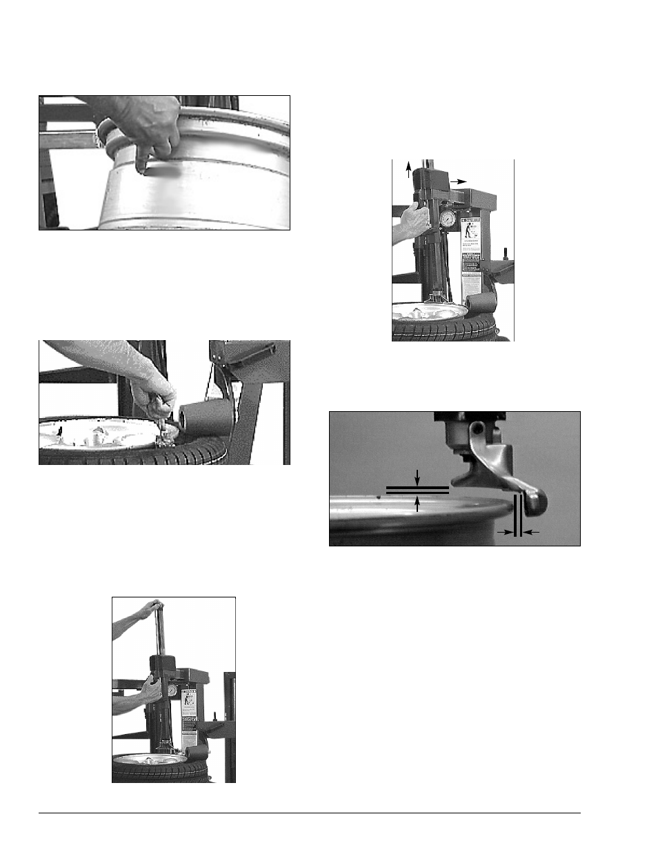
Figure 8 - Proper Mount/Demount Head Postion
9.
Check head positioning. Mount/demount head
should be positioned with 1/8 to 3/16" clearance
between the top of the rim edge and the bottom
of the head, and 1/8 to 1/4 inch clearance
between the rim edge and the head roller. This
clearance will be maintained as long as the slide
locking valve remains locked. The operator may
move the tower back out of the way and back
into place again without needing to reposition
the head (when changing a like set of wheels)
(Figure 8).
H. The tool clearance may change with machine
use and should be inspected often. Failure to
maintain the proper clearance may result in
damage to the wheel rim and/or tire.
4 • 9010 Rim Clamp Tire Changer
1/8" to 1/4"
1/8" to 3/16"