COATS 9010 AX/EX Tire Changer User Manual
Page 4
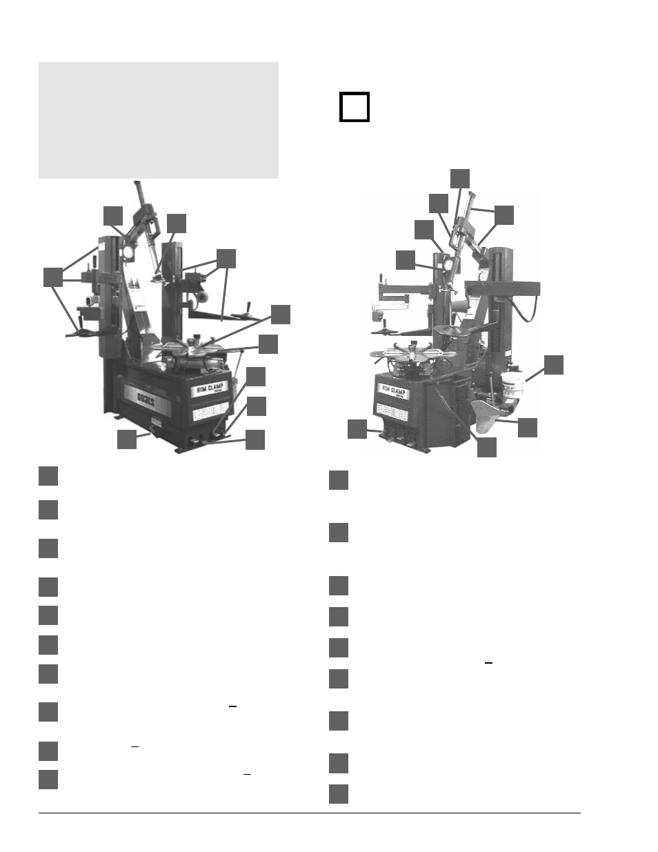
Principal Operating Part
Tower — Support for horizontal and vertical
slides.
Air Inflation Gauge — Registers tire pressure
when clip-on chuck is attached to valve stem
and inflation pedal is released.
Inflation Pedal — Three position pedal that
allows inflation of tires through air hose and
clip-on chuck.
Clamp Control Pedal — Three position pedal
that opens and closes rim clamps.
Table Top Pedal — Three position pedal that
controls rotation of table top.
Tower Tilt Pedal — Three position pedal that
moves tower forward and back.
Clamps — Secures wheel to table top for tire
changing. Adjust outward to allow outside
clamping of wheels up to 21 inches.
Left Helpers & Support
Includes
mount/demount helpers, slide, cylinder & valve
for operation.
Lube Bucket
Dispenser for rubber lubricant.
Combination Mount/Demount head
Mounts
and demounts tire from wheel. Adapted for
steel or nylon.
Slide Adjustment Handle — Adjusts Horizonal
/ vertical slide assembly for proper horizonal &
vertical positioning of mount / demount head.
Slide Locking Valve — Locks and unlocks
horizontal / vertical slide and sets correct
vertical / horizontal position to maintain head /
wheel clearance.
Bead Lifting Tool — Used to lift and position
tire bead correctly on mount/demount head.
Bead Loosener Shoe — Pivoting shoe for
loosening tire beads.
Bead Loosener Pedal — Controls operation of
bead loosener shoe.
Right Helpers & Support Includes mount/
demount roller & disk, slides, cylinder and valve
for operation.
Bead Sealing Nozzles — Expands tire
sidewall to bead seat area of rim to seal and
allow inflation.
Horizontal & Vertical Slides — Allows correct
positioning of mount / demount head.
Release Valve — Allows the manual release of
air pressure from tire.
2 • 9010 Rim Clamp Tire Changer
1
2
8
7
6
5
4
3
9
13
14
15
16
17
18
1
2
3
4
5
6
7
8
9
10
11
12
13
14
15
16
17
18
Know Your Unit
Compare this illustration with the unit before
placing it into service. Maximum performance
and safety will be obtained only when all per-
sons using the unit are fully trained in its parts
and operation. Each user should learn the func-
tion and location of all controls.
Prevent accidents and injuries by ensuring the
unit is properly installed, operated and main-
tained.
10
11
12
19
19
Do It Now!
Now is a good time to fill
out the Owner’s Registry
Card.
✓
12