Installation instructions – COATS Kit 8560761701 Robo-Arm LR User Manual
Page 2
2 •
Tire Changers
Installation Instructions
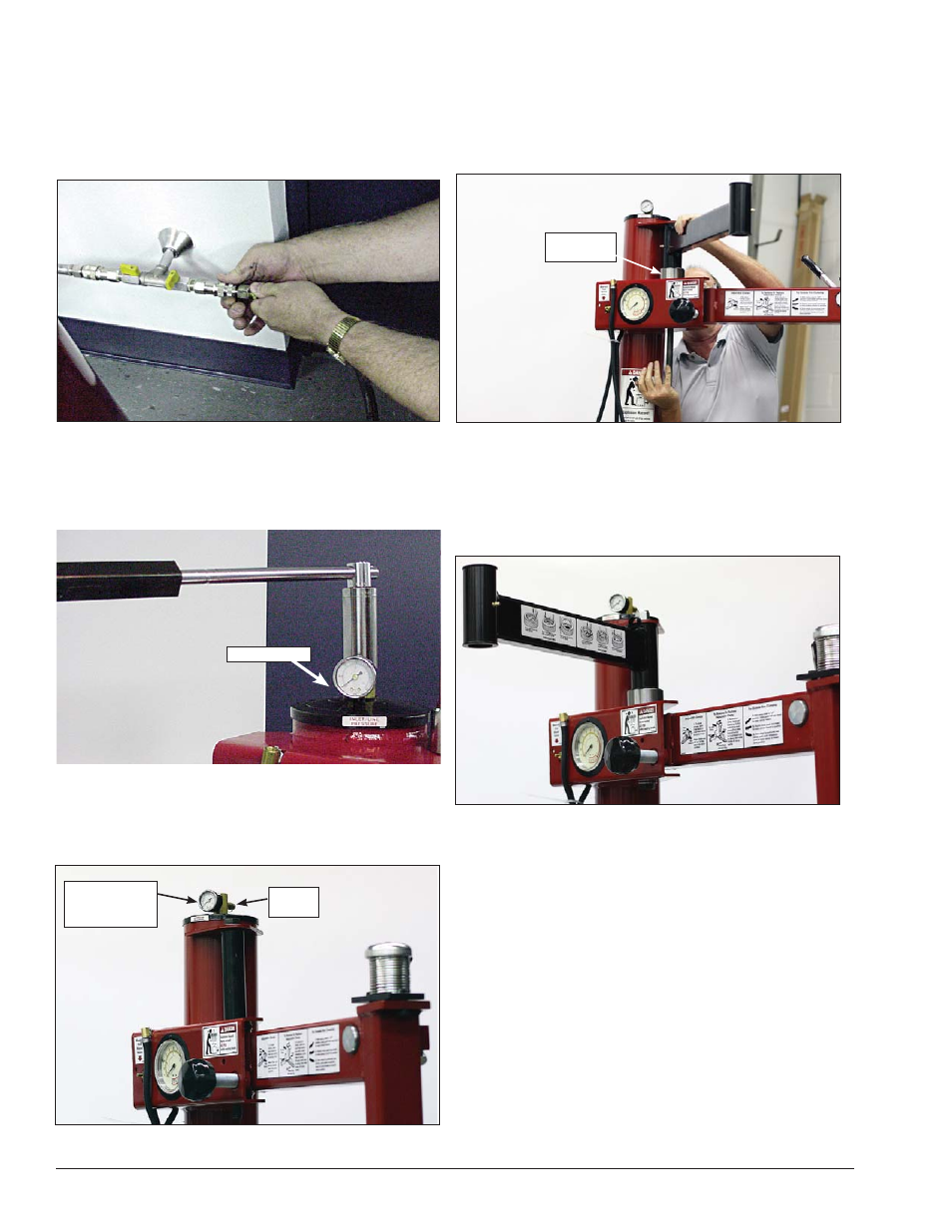
1.
Before beginning any work, clear the area and posi-
tion the machine for easy access. Disconnect all power
sources, both air and electricity inputs. Allow any stored
air in the reservoir to escape by depressing the inflate
valve.
Figure 1 - Disconnect power and air sources.
2.
Verify the stored air pressure is zero by observing
the air pressure gauge on top of the tower (see photo).
Next with a 1 1/16-inch socket wrench, remove the
manifold with the gauge and safety valve.
Figure 2 - Remove manifold with gauge and safety valve.
3.
Next install the included manifold with the gauge
and safety valve plus a barbed hose fitting. Tighten until
the barbed fitting is located as shown in photo.
Figure 3 - Install manifold, safety valve and barbed fitting.
4.
Next, remove nut on the bolt supporting the swing
arm pivot system. With the new 14-inch (356 mm) long
bolt push the old bolt out. Make sure the small washer
is on the head of the new bolt. Next, install the pivot pin
spacer, the swing arm (note position of the decal) with
pivot pin spacer, large washer and the lock nut.
Figure 4 - Use new long bolt to push old bolt out.
5.
Next, using large wrenches, tighten the assembly
to 240 ft. pounds torque (very tight). If the swing arm
rotation is too tight, loosen the lock nut until the swing
arm assembly rotates with a slight amount of resis-
tance.
Figure 5 - Tighten swing arm to rotate with some resistance.
Safety Valve
Manifold with
Gauge and
Safety Valve
Barbed
Fitting
Pivot Pin
Spacer