.5_tire mounting with hooked tool (optional) – COATS CDH-4730 Electric-Hydraulic Tire Changer User Manual
Page 16
16
7..5_Tire mounting with HOOKED TOOL (optional).
1) Make sure that the rim is clamped properly (see paragraph on “rim clamping”).
) lubricate both beads and rim with tire manufacturer recomended lubricant.
) Attach the g-clamp to the outside edge of the rim, at its highest point.
) Position the tire on the ramp and lower the spindle (make sure the g-clampis at the high point)
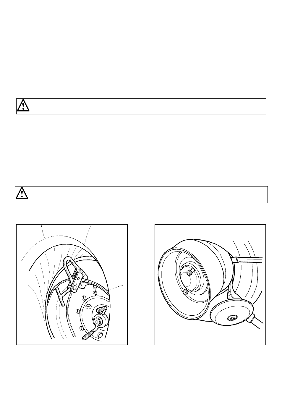
5) Lift the rim with the tire hooked to it, and turn it counterclockwise about 6-8 inches (15-20 cm.)
The tire will be positioned inclined across the rim.(fig. 27)- Move the tool arm into its non-working position, then move the carriagefowards the
spindle, so the arm is facing the in side face of the tire
6) Tip the tool-arm (17) in its working position until it will gets hooked.
Check that the arm is correctly hooked to the carriage
7) Check to make sure that the hook tool is positioned facing the bead. Otherwise reverse the locking pin and turn it of 180°.
8) By means of levers (3) and (4) move the tool forward until red reference dot is line up with the outside edge of the rim and about 1/4” (5 mm) from
it. (fig.28)
9) Move to teh outside of the tire assembly and check the exact position of the hook usually, and ajust it as needed then. Turn clockwise until the
g-clamp is atb the botton (6 o’clock). First bead will be now mounted on the rim. In case difficult, use the bead- lifting lever to facilitate sliding the bead
into the drop center.
10) Remove the g-clamp from the rim and move the carriage away from the tire, so that the hook tool comes out of it.
11) Tip the tool arm in non-working position, slide it to the outside face of the tire and fix it in this position.
DO NOT keep your hands on the tool when setting it in working position so as to avoid any possible crushing between tire and
tool.
1) Turn the tool of 180°, so that the hook is facing the outside face of the tire, then lock.
1) Move the tool foward until the red reference dot is lined up the outside edge of the rim and about 1/4” (5 mm) from it. (fig.29)
Fig.27
Fig.28