Direct drive, Caution – COATS 6401 Computer Truck Wheel Balancer User Manual
Page 10
Unpack and Setup the Unit
1. Install the two (2) hood springs.
2. Mount hood using the three (3) hex bolts (3/8-16 UNC x 1"),
matching hex nuts and lock washers supplied in the accessory
box.
3. Remove the bolts holding the balancer to the pallet. With a
forklift, carefully lift the balancer off the pallet and move to final
position.
Do not use the control pod, control pod arm, face-
plate, hood or stub shaft to lift the balancer.
4. Install and tighten the four (4) accessory pegs and hang the
accessories.
5. Install and tighten the threaded stud into end of motor
shaft.
6. Loosen the four 5/16" nuts and raise the control pod sup-
port arm. Raise it high enough to allow room for the pod to
rotate into position and for the Match Mount instructions to
lower below the pod.
7. Lightly tighten the control pod support arm retainer nuts on
the side of the support bracket. Arm will be adjusted and tight-
ened later.
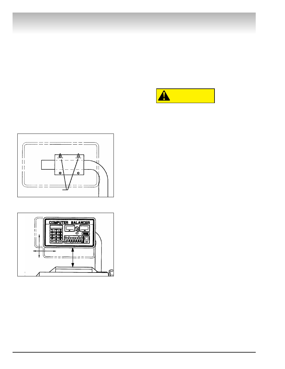
8. Loosen the two adjustment knobs on the back of the con-
trol pod (Figure 2).
9. Rotate the pod into operating position, and retighten the
knobs.
10. Loosen the nuts on the support arm retainers. Raise or
lower the control pod into the desired position, and tighten the
retainer nuts securely. The bottom edge of the pod should be at
least 8 inches above the top of the balancer (Figure 3).
11. Lower the Match Mount instructions attached to the
underside of the control pod. If there is not enough room
between the pod and the balancer weight tray to fully lower the
instruction card, the pod should be raised.
12. Position the balancer in its final operating location. Lightly
tighten the four 5/16" nuts
CAUTION
Direct Drive
4 • COATS 6401 Truck Wheel Balancer
Figure 2 - Control Pod Adjustment Knobs
Figure 3 - Control Pod Height
8" Min.
Adjustment Knobs