Caution, Installation – COATS 575 Heavy Duty Tire Lift User Manual
Page 6
6 • COATS Heavy Duty Tire Lift
Installation
Pneumatic Connection
Connect air intake to a compressed air system with
a working pressure of 120-150 PSI. Use a compressed
air hose with an inside diameter of 1/4” - 3/8”.
CAUTION
Make sure air hose is free of the BASE
TRACK area. If the air hose is damaged, the
Tire Lift may descend unexpectedly.
Assembly Instructions
Tools Required:
• F (0.257") or G (0.261") Size Drill Bit
• Center Punch
• Marker
• 9/16-inch Socket
• Ratchet
• 9/16-inch Combination Wrench
• Ruler
575 Heavy Duty Tire Lift Components:
• STORAGE BRACKET
• TOWER ASSEMBLY
• WHEEL TRAY
• BASE TRACK (with CARRIAGE INSERT)
• FASTENERS
1.
Position unit by your wheel balancer; then remove
BASE TRACK from pallet.
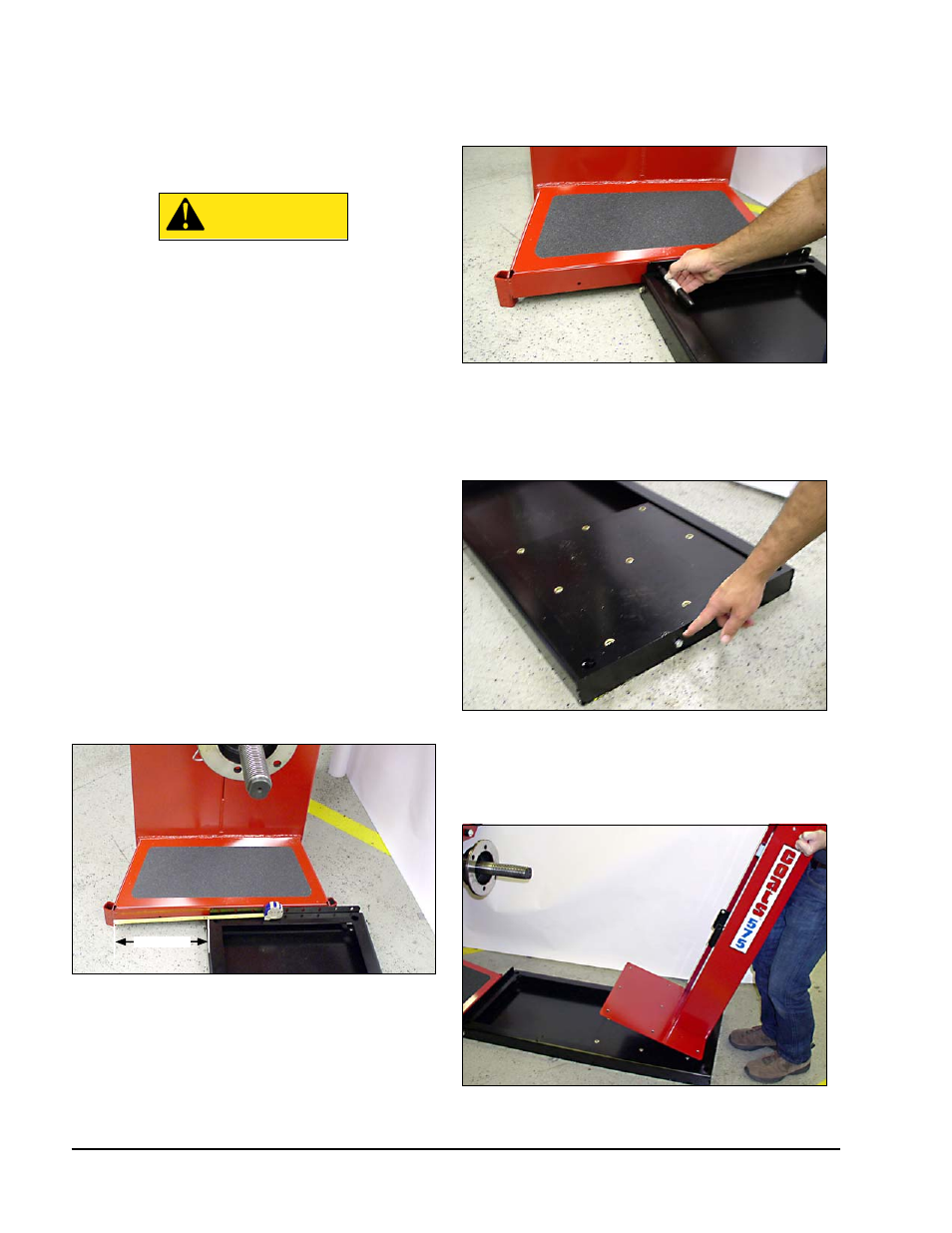
2.
Slide BASE TRACK so LIFT MOUNTING BRACKET
is up against the wheel balancer chassis; below the
stub shaft. With the aid of a tape measure, place the
BASE TRACK 12-inches from the balancer edge as
shown (fig 2).
Figure 2 - Position LIFT MOUNTING BRACKET Against Wheel
Balancer
3.
Mark two hole locations and use a size F (0.257")
or size G (0.261") drill bit to the drill holes. Choose the
LIFT MOUNTING BRACKET fastener hole locations
that are farthest apart from each other.
Figure 3 - Mark two drill hole locations
4.
Fasten base tray to balancer using two self-
tapping bolts.
5.
Remove and discard the shipping bolt at the end
of the BASE TRACK.
Figure 4 - Remove Shipping Bolt Holding CARRIAGE INSERT
6.
Remove pivot bolt from WHEEL TRAY and set
WHEEL TRAY and pin aside.
7.
Now place the TOWER ASSEMBLY on the CAR-
RIAGE INSERT as shown.
Figure 5 - Position TOWER ASSEMBLY on CARRIAGE INSERT
12-inches