Warning, Operation – COATS 550 Heavy Duty Tire Lift User Manual
Page 5
COATS Heavy Duty Lift • 5
4.
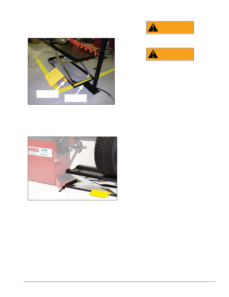
Locate storage tower and hardware. Stand stor-
age tower up and assemble it to the frame using the
hardware (Fig. G).
5.
Locate wheel ramp and hardware. Attach wheel
ramp to lift assembly as shown (Fig. G).
Figure G - Fasten Tower and Wheel Ramp to Lift Assembly
6.
Fasten lift to balancer (Fig. H). Position lift against
the wheel balancer; aligning the two holes on the plate
with the two holes on the balancer. Secure using (2)
3/8-16 x 1-1/2 HHCS screws, (4) 3/8 plain washers and
(2) 3/8-16 Nyloc hex lock nuts.
Figure H - Fasten Heavy Duty Lift Assembly to COATS®
Wheel Balancer
Note: The COATS 6401 wheel balancer requires the
550 Heavy Duty Lift Adapter Kit 85607401 to attach the
lift to the wheel balancer.
Pneumatic Connection
Connect air intake to a compressed air system with
a working pressure of 120-150 PSI. Use a compressed
air hose with an inside diameter of 1/4” - 3/8”.
Important: Make sure the air hose is free of the track
area. If the air hose is damaged, the lift may descend
unexpectedly.
Operation
WARNING
Before moving the carriage, make sure the
track area is clear of debris.
WARNING
Do not put your hands on the top of the
wheel, during this operation. Your hand
could be pinched between the wheel and
the carriage handle.
550 Heavy Duty Lift Operation
1.
Use carriage handle to slide the carriage back away
from the balancer; aligning it with the wheel ramp.
2.
Push the valve handle downward; making sure the
carriage assembly is completely lowered.
3.
Roll the wheel assembly over the wheel ramp to
load it onto the carriage.
4.
Push the valve handle upward to raise the wheel
assembly; centering it with the balancer stub shaft.
5.
Use the carriage handle to slide the carriage for-
ward until the wheel assembly is on the balancer stub
shaft; ready to be mounted on the balancer.
6.
Secure the wheel to the balancer using suitable
mounting adapters.
7.
Push the valve handle downward so the carriage
no longer contacts the wheel assembly.
8.
Move the carriage back out of the wheel balancer
work area.
9.
Balance the wheel.
10.
Use the carriage handle to move the carriage
forward; under the wheel assembly.
11.
Push the valve handle upward so the carriage
will support the wheel assembly.
12.
Remove the wheel assembly from the balancer
stub shaft.
13.
Use the carriage handle to slide the carriage
back away from the balancer; aligning it with the wheel
ramp.
14.
Push the valve handle downward; making sure
the carriage assembly is completely lowered.
15.
Unload the wheel assembly by rolling it out of
the carriage and down the wheel ramp.
Fasten Wheel
Ramp to Lift
Fasten Tower
to Lift
Fasten Lift to
Wheel Balancer