Warning, Installation – COATS 550 Heavy Duty Tire Lift User Manual
Page 4
4 • COATS Heavy Duty Lift
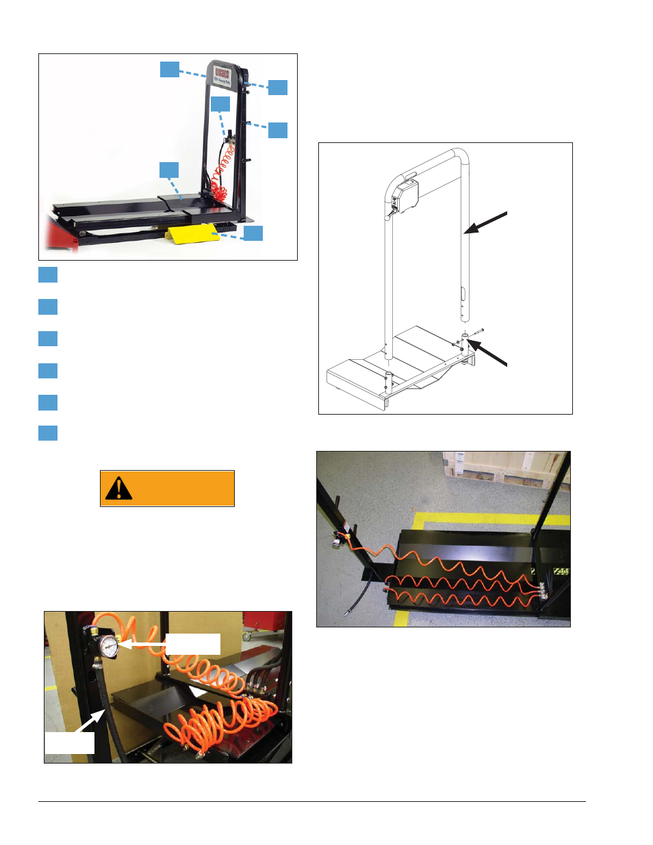
Principal Operating Parts
1
Carriage Handle — Use to slide the lift carriage
back and forth.
2
Valve Handle — Push up to raise or down to
lower the lift carriage assembly.
3
Pressure Regulator — This safety device is set
by the user to regulate the PSI range.
4
Accessory/Cone Peg Tower — Convenient stor-
age location for cones and accessories.
6
Carriage — Support for wheel assembly.
5
Wheel Ramp — Used when loading/unloading a
wheel assembly to/from the carriage.
Safety Device
WARNING
Removing or tampering with this safety
device may lead to personal injury and
damage to property
This wheel lift is equipped with a pressure regula-
tor device (Fig. C) that prevents air supply pressures
higher than the user setting. The user PSI setting for
the pressure regulator valve is from 120 to 150 PSI.
Figure C - Pressure Regulator
Installation
Assembly
1.
Position unit by your wheel balancer and remove
from crate.
2.
Locate carriage handle and hardware. Slide handle
assembly onto post of lift and assemble using pack-
aged hardware (Fig. D).
Figure D - Carriage Handle Assembly Diagram
3.
Connect air hoses as shown in Fig. E.
Figure E - Connect Air Hoses
3
4
1
2
5
6
Carriage
Handle
Attach to
Post of Lift
Pressure
Regulator
Air Intake
Hose