Pro racer – COATS 950 Pro Racer Wheel Balancer User Manual
Page 9
Connect to Power
20. Connect the balancer to an appropriate electrical recep-
tacle. Refer to Figure 5, as well as Electrical Requirements on
page 2.
NOTE: If pedestrian or equipment traffic might damage the
standard power cord, power outlets must be enclosed in a race-
way on the floor or in an overhead drop.
NOTE: Electric outlets must be solidly connected. There
should be less than 1
Ω
between the ground pin and earth
ground. The installer or electrical inspector must verify the out-
let installation before connecting the balancer. Failure due to
improper power connection will void the warranty.
NOTE: The green wire in the cord is the grounding wire. Never
connect the green wire to a live terminal.
Initial Testing
Your Hennessy Territory Manager should do the final check to
verify the power installation before connecting the balancer.
Failure due to improper power connection will void the warranty.
21. If the circuit breaker for the balancer outlet is off, turn it
on now. Turn the balancer ON/OFF switch to ON.
REMEMBER: To maintain the proper operating temperature for
the balancer, the unit should be left on all day.
22. The displays will show zeros when the unit is first turned
on. Press any key to continue.
23. Verify that the fan is running by placing your hand
between the arbor faceplate and the motor housing. You should
feel air coming out from around the motor housing. Do not oper-
ate the balancer if airflow is not present when the balancer is
on.
24. Press START. The arbor faceplate should spin in the direc-
tion indicated by the label at the outer edge of the motor cover
(clockwise when viewed straight on).
NOTE: Disregard a short spin cycle with “HUB” displayed on
the control panel during this initial testing.
Pro Racer
COATS 950 Pro Racer Wheel Balancer • 3
Figure 4 - Control Pod Height
8" Min.
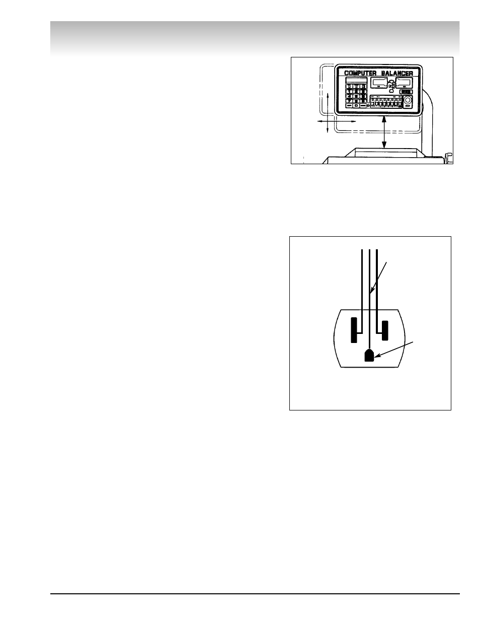
Figure 5 - Single-Phase Wiring Diagram
Rear View
White
Green Or
Green/Yellow
Black
Ground
A - B
105 - 130 VAC
Outlet