B&W Trailer Hitches 1059R User Manual
Page 4
Copyright 2014
B&W Custom Truck Beds, Inc.
ALL RIGHTS RESERVED
1059R 05 01 2014
STEP TEN - INSTALL SAFETY CHAIN BRACKETS
To install the safety chain brackets it is necessary to drill four
1/2” holes through the truck bed floor. Drill the holes from
beneath the truck, through the two holes located on each side
and closest to the round receiver tube in the center sec-
tion. This will locate the safety chain brackets in the lowest
point of the floor corrugation. Drop a U-bolt through each pair
of holes from the topside of the truck bed floor. Place a spring
and lock nut on each of the four legs. Tighten the lock nuts
until flush with the bottom of the U-bolts.
STEP ELEVEN - REPLACE THE EXHAUST BRACKET
Replace the exhaust hanger brackets and the spare tire if removed during step 2 of the installation.
STEP EIGHT
Install the ½-inch x 6 ¼-inch U-bolt from inside the frame through the holes in the
sideplate above and below the frame, use a lock washer and nut on each end of the U-
bolt. Repeat this procedure on the passenger side of the truck with the other sideplate.
(While installing the U-bolts around the frame use caution not to damage or pinch the
wiring harness or brake lines). Install the ¾-inch by 2 ½-inch bolt. Place a flat washer
and frame insert on the 3/4” bolt and install the bolt from inside the frame through the
rear hole in the side plate. The 3/4” bolt fastens with a lock washer and nut. (The holes
in the frame and the sideplate are slotted and B&W provides an insert that converts the
slotted holes to a 3/4” round hole. When installed correctly the frame insert will seat firmly in
the slotted hole in the frame and the slotted hole in the sideplate). When completed, tighten
all the hardware in this order: 1. Tighten the center section bolts to the cross members to
80 ft pounds. 2. Make certain the hitch is square with the frame. 3. Tighten the ¾” side plate
bolts to 120 ft pounds. 4. Tighten the frame clamping U-bolts slowly, alternating between
the top and bottom legs of the U-bolt until equally tightened to 40 ft pounds. 5. Tighten the
three carriage bolts on each side to 60 ft pounds. 6. Tighten the side plate to the front and
rear cross members to 80 ft pounds.
LATCH
PIN
TAB
IN−LINE
DRIVER SIDE
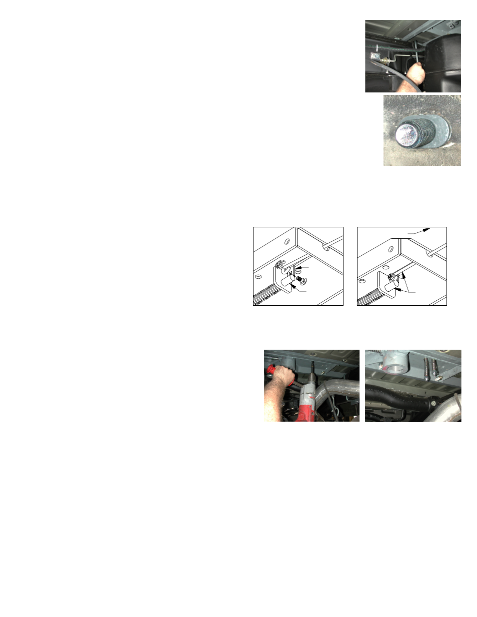
STEP NINE – INSTALL LATCH PIN RELEASE HANDLE
WARNING: LATCH PIN WILL NOT FUNCTION PROPERLY IF HANDLE IS NOT INSTALLED CORRECTLY.
Install the latch pin release handle by inserting it through the
slot in the end of the center section on the driver’s side of the
truck. Align the handle eyelet with the square hole in the latch
pin so the handle is in line with the latch pin as shown. Secure
the handle to the pin with the 5/16 X 3/4” carriage bolt and
5/16” locking flange nut as shown. Note: The included 5/16”
cap screw can replace the carriage bolt if wrench access on
the “cab side” of the handle is limited. Tighten the nut until it
is secure. Do not over-tighten and deform the handle eyelet.