Application update – B&W Trailer Hitches 1059R User Manual
Page 3
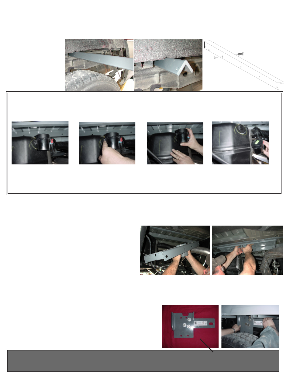
STEP FIVE - CROSS MEMBER INSTALLATION
Place the 48” front cross member between the truck frame and bed floor using the notch made in step four. Be sure the
holes in the cross member are facing to the rear of the truck. Slide the cross member across both frame rails. Using the
rubber O-ring provided, secure a 1/2” x 1 1/2” long bolt into the second hole in the cross member from the driver’s side.
Slide the crossmember forward to the front edge of the 4” hole in the bed. Next install the 46 1/2
”
rear cross member
bar between the truck frame and bed floor. Rotate the rear cross member a quarter turn so the threaded holes are offset
to the bottom of the bar
and slide back until there
is enough room for the
center section to be
placed between the two
cross members.
STEP SIX - CENTER SECTION INSTALLATION
Raise the center section into position between the crossmembers and carefully move it above the fuel tank from
beneath the truck. The receiver socket must be positioned to the rear with the latch pin release arm on the driver’s
side. A lifting device, as described on Page 1 will help. The round hitch receiver that protrudes from the top of the
center section must fit through the hole in the truck bed floor. Slide the front cross member back against the center
section so that the bolt installed previously in the front
cross member goes into the center section hole directly
across from it. Line up the rest of the holes and attach
the two members with 1/2” x 1 1/2” long bolts, lock
washers, and nuts. Insert 1/2” x 1 1/2” bolts, with flat
and lock washer installed, through the rear leg of the
center section into the threaded holes of the rear cross-
member and hand tighten.
STEP SEVEN - INSTALL SIDEPLATES
Next install the sideplates. The driver’s sideplate is shown, with the bent flange to the front, and the large hole to the
rear. Attach the two pieces of the sideplate together with ½” carriage bolts. The carriage bolts should be inserted into
the square holes from the backside of the sideplates and fastened using a flat washer, lock washer and nut on each
bolt. This can be completed before installation on the frame rail.
Do not tighten at this time. Attach the flange on the sideplate to
the front cross member using a ½ x 1 1/2 inch bolt, flat washer,
lock washer and nut. Insert the bolt through the flange so that
the nut when tightened is on the front side of the cross member.
Next attach the rear bar to the sideplate ear threading a ½ inch
by 1 ½ inch bolt with flat and lock washer installed into the bar.
Installation Note: 1999-2003 Light Duty
1/2 & 3/4 Ton Trucks
2004 Light Duty 3/4 Ton Trucks
Install the side plate on the Light Duty Trucks by utilizing the U-
bolt placement holes at the rear of the side plate. Front placement
holes are for Standard 1/2 Ton applications.
Step 1:
Locate the fuel valve.
Step 2:
Disengage the lock-
ing pin.
Step 3:
Slide fuel valve from
bracket.
APPLICATION UPDATE:
Beginning in 2004, a fuel valve mounted on the rear of the fuel tank on trucks equipped with gas engines, makes
it more difficult to install the Turnoverball™ center section. This fuel valve can be easily removed and replaced to
ease installation. Please follow the following instructions:
Step 5: Replace fuel valve to bracket on fuel tank.
Step 4:
Install Turnoverball™
Center Section.