Before installing, Installation instructions – B&W Trailer Hitches 1059R User Manual
Page 2
BEFORE INSTALLING
OVERHEAD LIFTING DEVICE
An overhead-lifting device, such as chain falls, engine hoist, or cable come-a-long, can be used to lift the center section of the
hitch in place. Lower a loop of rope or chain through the 4” hole in the truck bed floor and attach it to the latch pin in the round
hitch receiver tube in the center section. Use the lifting device to raise the center section until the round hitch receiver tube that
protrudes from the center section fits in the 4” hole in the truck bed floor. Maintaining upward pressure may facilitate fastening the
crossmember to the center section, especially if the truck bed floor has been distorted downward from heavy use. If you use an
overhead-lifting device, it should be disconnected before squaring the center section across the frame, installing the sideplates and
torquing fasteners.
WARNING
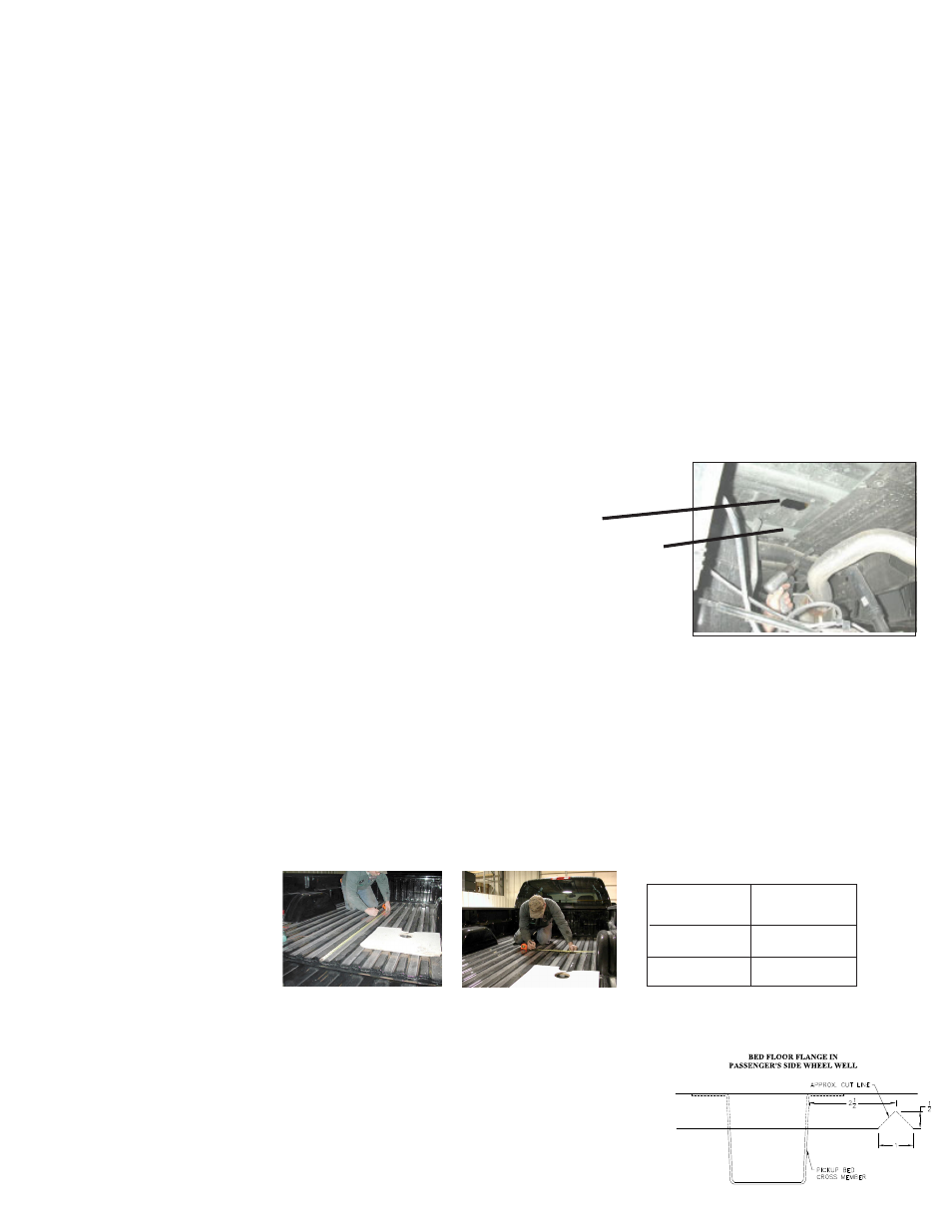
Most trucks have FUEL LINES and/or BRAKE LINES and/or ELECTRICAL WIRES located along the frame rails where B&W Turnover-
ball™ hitches install. Carefully examine the location of fuel lines, brake lines and electrical wires BEFORE INSTALLATION. Be certain
you will not damage fuel lines, brake lines or electrical wires when positioning hitch components, drilling holes and tightening fas-
teners. The fuel tank vent, located on top of the gas tank, can be easily damaged during the installation of the hitch components.
Care must be taken when positioning the front crossmember and center section components.
INSTALLATION INSTRUCTIONS
STEP ONE - REMOVE SPARE TIRE AND HEAT SHIELD
The heat shield under the bed floor must either be removed or a section cut out for
the hitch assembly to be installed.
A) Remove the heat shield from in front of the back crossmember.
B) Remove the heat shield from the back of the crossmember located near the
front of the wheel well.
STEP TWO - REMOVE EXHAUST BRACKET
To ease installation of the center section it is necessary to remove the lower exhaust
bracket. Simply pull the hanger rod out of the rubber bracket hole, a 6” to 8” wood
block can then be positioned between the exhaust pipe and frame of the truck. This
will increase your clearance between the top of the exhaust pipe and the bottom of
the truck bed floor. (Caution: Exhaust pipe may be hot).
STEP THREE- MARKING AND CUTTING 4 INCH HOLE IN TRUCK BED
Begin by verifying and measuring the correct hole location in the truck bed floor. Measure from the back end (tailgate
end) of the truck bed floor by hooking a tape measure over the back of the truck box and mark the floor at the correct
measurement. Next, center the location between the wheel wells. This will be the center point for the four inch hole.
This location is critical to the correct installation of this hitch, so measure, mark and saw carefully. If the truck has
a plastic bed liner, you may drill through both, but it is more difficult to accurately locate the midpoint between the
fender wheel wells, and to be sure that the bed liner does not move while sawing the hole. Make a 4 inch hole at this
location using a four inch hole saw, or by marking a 4 inch circle and cutting it out with a saber saw equipped with a
metal cutting blade.
TIP: B&W uses a 3/4”
piece of plywood as a
drilling guide to prevent
the hole saw from moving
while drilling the 4” hole
in the bed.
Install the two cross members. They will be installed by sliding them from inside the wheel well, above the tire, through
the gap between the bed and the truck’s frame and across until they span the frame
rails. The gap between the bed and frame is large enough to allow this, but the gap
is partially obstructed by a sheet metal flange (about 1” in height) that is hanging
down from the bottom of the truck bed floor. (See diagram and photos). A small notch
needs to be made in this flange on the passenger side of the truck. Locate the center
truck bed cross member. Measure over 2 1/2” from the front of the cross member
and make a mark. This will be the center point of the notch that is needed. Mark a
1” wide by 1/2” tall notch. Remove the metal of the marked area with sheet metal
shears. This will allow the front angle iron crossmember to be installed.
STEP FOUR-CROSS MEMBER INSTALLATION
Long Bed 49 1/2”
Truck
Ball
Type
Location
Short Bed 44 1/4”
WARNING
On Short bed trucks, BEFORE INSTALLING THIS HITCH, check for adequate turning clearance between the front of all
of your trailers and the truck cab.
WARNING
DO NOT invert the ball in the socket when carrying heavy loads on 2 wheel drive trucks. The ball may hit the top of
the differential. Remove the ball from the socket before loading. A plug for the socket is available from B & W.