Oscillating axle lockout test, 3 free wheeling option, Oscillating axle lockout test -3 – JLG 800A_AJ ANSI Service Manual User Manual
Page 59: Free wheeling option -3
SECTION 3 - CHASSIS & TURNTABLE
3120740
– JLG Lift –
3-3
Oscillating Axle Lockout Test
LOCKOUT SYSTEM TEST MUST BE PERFORMED QUARTERLY,
ANY TIME A SYSTEM COMPONENT IS REPLACED, OR WHEN
IMPROPER SYSTEM OPERATION IS SUSPECTED.
NOTE: Ensure boom is fully retracted, lowered, and cen-
tered between drive wheels prior to beginning lock-
out cylinder test.
1. Place a 6 inch (15.2 cm) high block with ascension
ramp in front of left front wheel.
2. From platform control station, activate machine
hydraulic system.
3. Place FUNCTION SPEED CONTROL and DRIVE
SPEED/TORQUE SELECT control switches to their
respective LOW positions.
4. Place DRIVE control lever to FORWARD position
and carefully drive machine up ascension ramp until
left front wheel is on top of block.
5. Carefully activate SWING control lever and position
boom over right side of machine.
6. With boom over right side of machine, place DRIVE
control lever to REVERSE and drive machine off of
block and ramp.
7. Have an assistant check to see that left front wheel
remains locked in position off of ground.
8. Carefully activate SWING control lever and return
boom to stowed position (centered between drive
wheels). When boom reaches center, stowed posi-
tion, lockout cylinders should release and allow
wheel to rest on ground, it may be necessary acti-
vate DRIVE to release cylinders.
9. Place the 6 inch (15.2 cm) high block with ascension
ramp in front of right front wheel.
10. Place DRIVE control lever to FORWARD and care-
fully drive machine up ascension ramp until right
front wheel is on top of block.
11. Carefully activate SWING control lever and position
boom over left side of machine.
12. With boom over left side of machine, place DRIVE
control lever to REVERSE and drive machine off of
block and ramp.
13. Have an assistant check to see that right front wheel
remains locked in position off of ground.
14. Carefully activate SWING control lever and return
boom to stowed position (centered between drive
wheels). When boom reaches center, stowed posi-
tion, lockout cylinders should release and allow
wheel to rest on ground, it may be necessary acti-
vate DRIVE to release cylinders.
15. If lockout cylinders do not function properly, have
qualified personnel correct the malfunction prior to
any further operation.
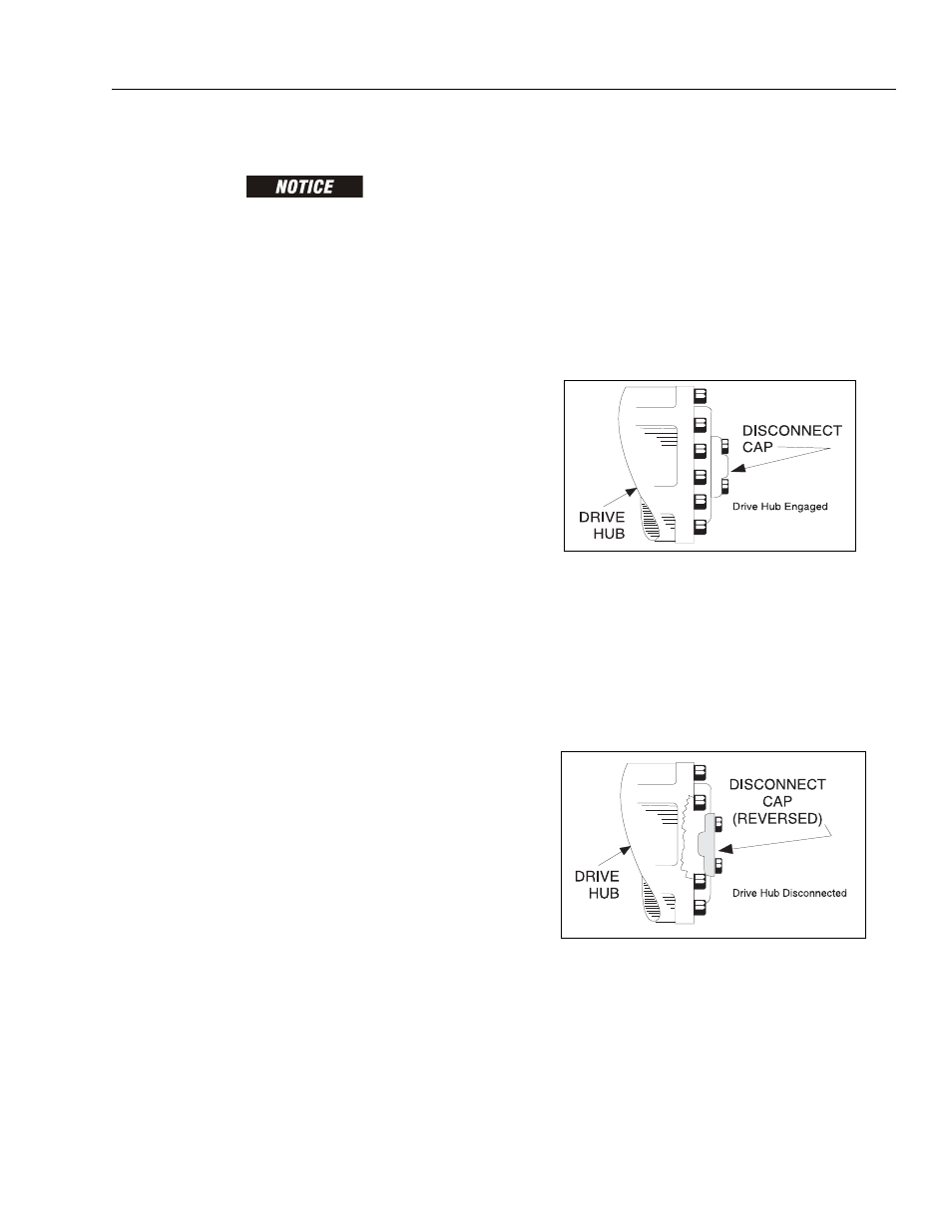
3.3 FREE WHEELING OPTION
To Disengage Drive Motors and Brakes (Free
Wheel) for Emergency Towing
1. Chock wheels securely if not on flat level surface.
2. Disconnect both drive hubs by reversing the discon-
nect caps in the center of the hubs.
To Engage Drive Motors and Brakes (Normal
Operation)
1. If equipped, move steer/tow valve to steer position
by pushing valve knob in.
2. Connect both drive hubs by inverting disconnect
cap in center of hub.
3. Remove chocks from wheels as required.