Assembly, Assembly -26, Actuator timing -26 – JLG 800A_AJ ANSI Service Manual User Manual
Page 240
SECTION 4 - BOOM & PLATFORM
4-26
– JLG Lift –
3120740
Assembly
NOTE: Lubricate all seals and o-rings with clean hydraulic
oil prior to assembly.
1. Install piston seal (7) and rod seal (6) on the piston
sleeve (3).
NOTE: Apply a coat of grease to the thrust ring before slid-
ing onto the shaft.
2. Install new seal (8), thrust ring (10) and bearing (9)
on shaft (2).
NOTE: Apply a coat of grease to the thrust ring before slid-
ing onto the end cap.
3. Install new seals (11), back-up ring (12), cap bearing
(13), bearing packing (14) and thrust ring (10) on
end cap (5).
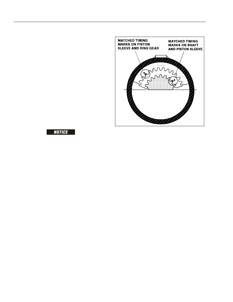
4. Place the actuator in the vertical position, install the
piston sleeve (3) in timed relation to the housing (1).
DO NOT MISALIGN THE SLEEVE TOO MUCH ANY ONE WAY, AS IT
WILL MARK THE CYLINDER BORE.
NOTE: The timing marks (the small punch marks on the
face of each gear), must be aligned for proper shaft
orientation. (See Actuator Timing.)
5. Install the shaft (2) into housing (1) by aligning the
proper punched timing marks. (See Actuator Timing
Figure 2-35.)
6. Temporarily tape the threaded portion of the shaft
will help installation past the shaft seals (masking
tape).
7. The end cap (5) is torqued to 40 - 50 ft. lbs. (54 - 68
Nm), such that the actuator begins rotation at
approximately 100 psi (6.895 Bar) pressure.
8. The end cap must be secured against the shaft by
installing axial set screws (4).
Figure 4-17. Actuator Timing