Epr assembly -138 – JLG 800A_AJ ANSI Service Manual User Manual
Page 194
SECTION 3 - CHASSIS & TURNTABLE
3-138
– JLG Lift –
3120740
Electronic Pressure Regulator (EPR)
Assembly Replacement
The EPR assembly is a made up of two separate compo-
nents. The Voice Coil Section is not serviceable and can
only be replaced as an assembly. The pressure regulator
section is serviceable and will be detailed in this section.
REMOVAL
1. Relieve the propane fuel system pressure. Refer to
Propane Fuel System Pressure Relief.
2. Disconnect the negative battery cable.
3. Slowly remove the fuel inlet fitting at the Electric
Lock Off.
NOTE: Residual vapor pressure will be present in the fuel
system.
4. Disconnect the electrical connector to the Electric
Lock off.
5. Remove the Electric Lock Off from the regulator.
6. Remove the lock pin from the vapor fitting on the
regulator housing and remove the fitting and hose
and retain the pin.
7. Remove the lock pin from the pressure sensor on
the regulator housing and remove the Sensor and
retain the pin.
8. Using a clamp pliers pinch off the hoses on the cool-
ant lines to the regulator.
9. Remove the lock pin from both the water fittings on
the regulator housing and remove the fittings and
hoses and retain the pin.
10. Disconnect the EPR electrical connector.
11. Remove the (3) three nuts from the EPR isolators
and the EPR mounting bracket.
12. Remove the EPR from the bracket.
13. Remove the (3) three mounting isolators.
INSTALLATION
DO NOT USE TEFLON TAPE ON ANY FUEL FITTING. USE A LIQUID
PIPE THREAD SEALANT WHEN INSTALLING FITTINGS.
CHECK ALL THE O-RINGS ON THE VAPOR AND WATER FITTINGS
FOR ANY DAMAGE REPLACE IF NECESSARY.
LUBE ALL THE O-RINGS WITH AN O-RING LUBE BEFORE
INSTALLING.
1. Install the three (3) rubber isolators to the bottom of
the EPR
2. Install the EPR assembly to the bracket and tighten
the retaining nuts.
NOTE: Do not over tighten the isolators and cause a separa-
tion of the isolators.
3. Install the fuel temperature sensor into the regulator
opening and lock in place with the locking pin, con-
nect the electrical connector.
4. Insert the fuel vapor line and fitting into the regulator
port and lock in place with the locking pin.
5. Install both the water hoses and fittings into the reg-
ulator and lock in place with the locking pin remove
the clamp pliers from the hoses.
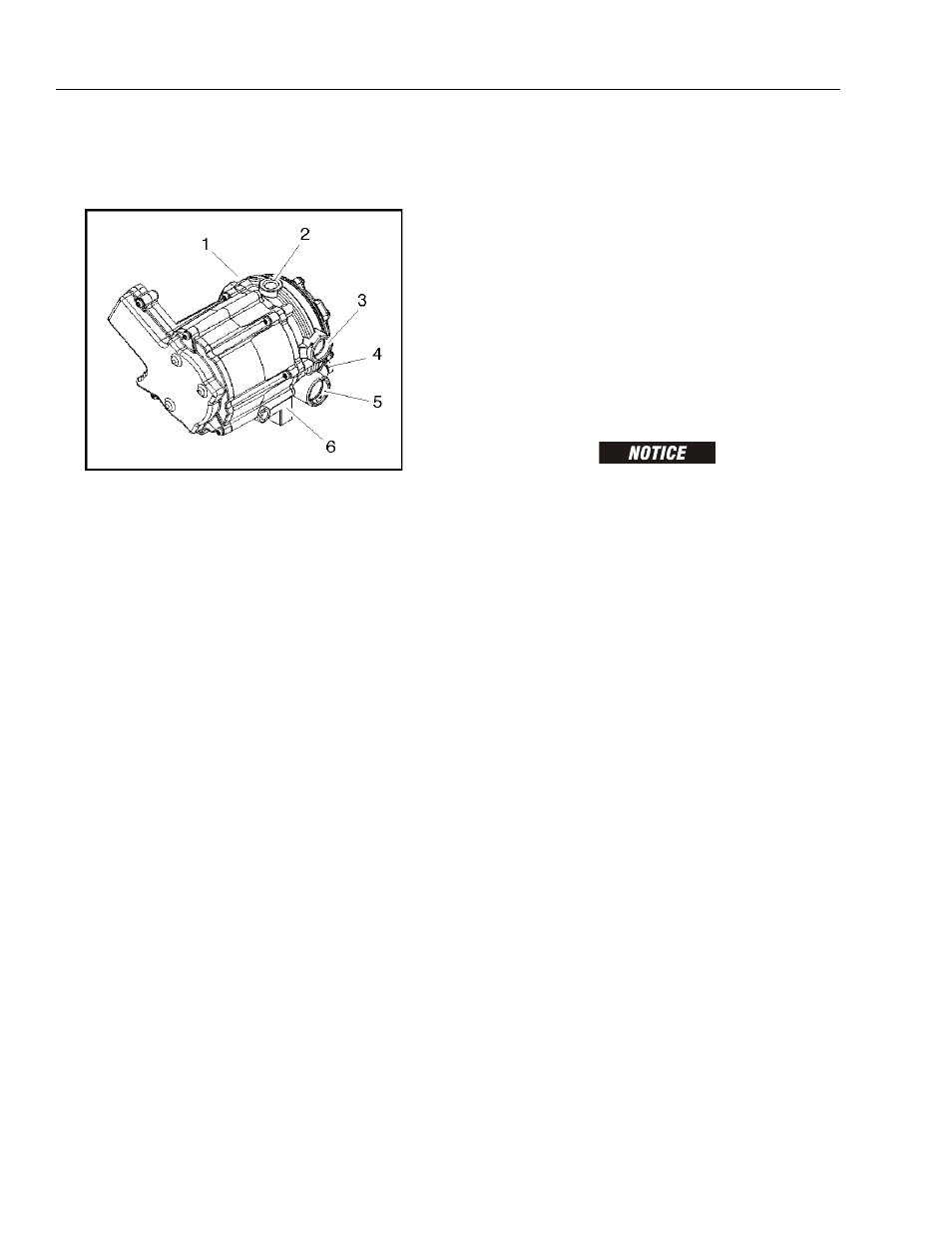
1. Pressure Regulator Section
2. Fuel Inlet
3. Coolant Passage
4. Primary Test Port
5. Secondary Test Port
6. Voice Coil Section
Figure 3-82. EPR Assembly