3 upper boom powertrack, Removal, 4 upper boom – JLG 800A_AJ ANSI Service Manual User Manual
Page 218: Upper boom powertrack -4, Removal -4, Upper boom -4, Boom power track components -4, 3 upper boom powertrack removal, 4 upper boom removal
SECTION 4 - BOOM & PLATFORM
4-4
– JLG Lift –
3120740
3. Supporting the rotator, remove the hardware from
pin #2. Using a suitable brass drift and hammer,
remove pin #2 from the fly boom and remove the
rotator.
4. Telescope the fly section out approximately 20
inches (50.8 cm) to gain access to the slave leveling
cylinder. (800 AJ only)
5. Supporting the slave, cylinder remove the hardware
from pin #3. Using a suitable brass drift and ham-
mer remove pin #3 from the fly boom.
6. Tag and disconnect hydraulic lines to the slave level-
ing cylinder. Use a suitable container to retain any
residual hydraulic fluid. Cap hydraulic lines and
ports. Remove the slave cylinder.
4.3 UPPER BOOM POWERTRACK
Removal
1. Disconnect wiring harness connectors located in
tower upright.
HYDRAULIC LINES AND PORTS SHOULD BE CAPPED IMMEDI-
ATELY AFTER DISCONNECTING LINES TO AVOID ENTRY OF CON-
TAMINANTS INTO SYSTEM.
2. Tag and disconnect hydraulic lines from connectors
at boom assembly. Use suitable container to retain
any residual hydraulic fluid. Cap hydraulic lines and
ports.
3. Disconnect dual capacity indicator limit switch from
side of boom section. (800A only)
4. Remove hydraulic lines and electrical cables from
powertrack.
5. Using suitable lifting equipment, adequately support
powertrack weight along entire length.
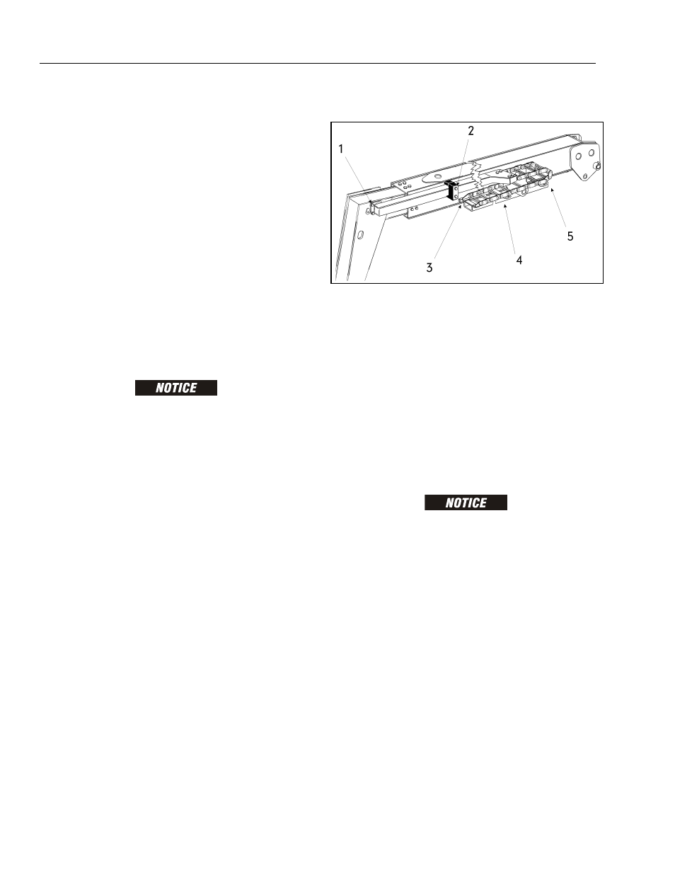
6. Remove bolt #1 securing the push tube on the fly
boom section.
7. Remove bolt #2 securing the push tube on the mid
boom section.
8. With powertrack supported and using all applicable
safety precautions, remove bolts #3, #4 and #5
securing rail to the base boom section. Remove
powertrack from boom section.
4.4 UPPER BOOM
Removal
1. Using a suitable lifting equipment, adequately sup-
port boom assembly weight along entire length.
HYDRAULIC LINES AND PORTS SHOULD BE CAPPED IMMEDI-
ATELY AFTER DISCONNECTING LINES TO AVOID ENTRY OF CON-
TAMINANTS INTO SYSTEM.
2. Tag and disconnect hydraulic lines from telescope
cylinder. Use suitable container to retain any resid-
ual hydraulic fluid. Cap hydraulic lines and ports.
Figure 4-5. Boom Power Track Components