20 tilt alarm switch (prior to s/n 0300065534), Manual adjustment, 21 spark arrester cleaning instructions – JLG 800A_AJ ANSI Service Manual User Manual
Page 142: Tilt alarm switch (prior to s/n 0300065534) -86, Manual adjustment -86, Spark arrester cleaning instructions -86, Tilt switch adjustment -86, Coupling port information table -86
SECTION 3 - CHASSIS & TURNTABLE
3-86
– JLG Lift –
3120740
3.20 TILT ALARM SWITCH (PRIOR TO S/N
0300065534)
PERFORM TILT ALARM SWITCH LEVELING PROCEDURE A MINI-
MUM OF EVERY SIX MONTHS TO ENSURE PROPER OPERATION
AND ADJUSTMENT OF SWITCH.
Manual Adjustment
1. Park the machine on a flat, level surface. Ensure
machine is level and tires are filled to rated pressure.
NOTE: Ensure switch mounting bracket is level and securely
attached.
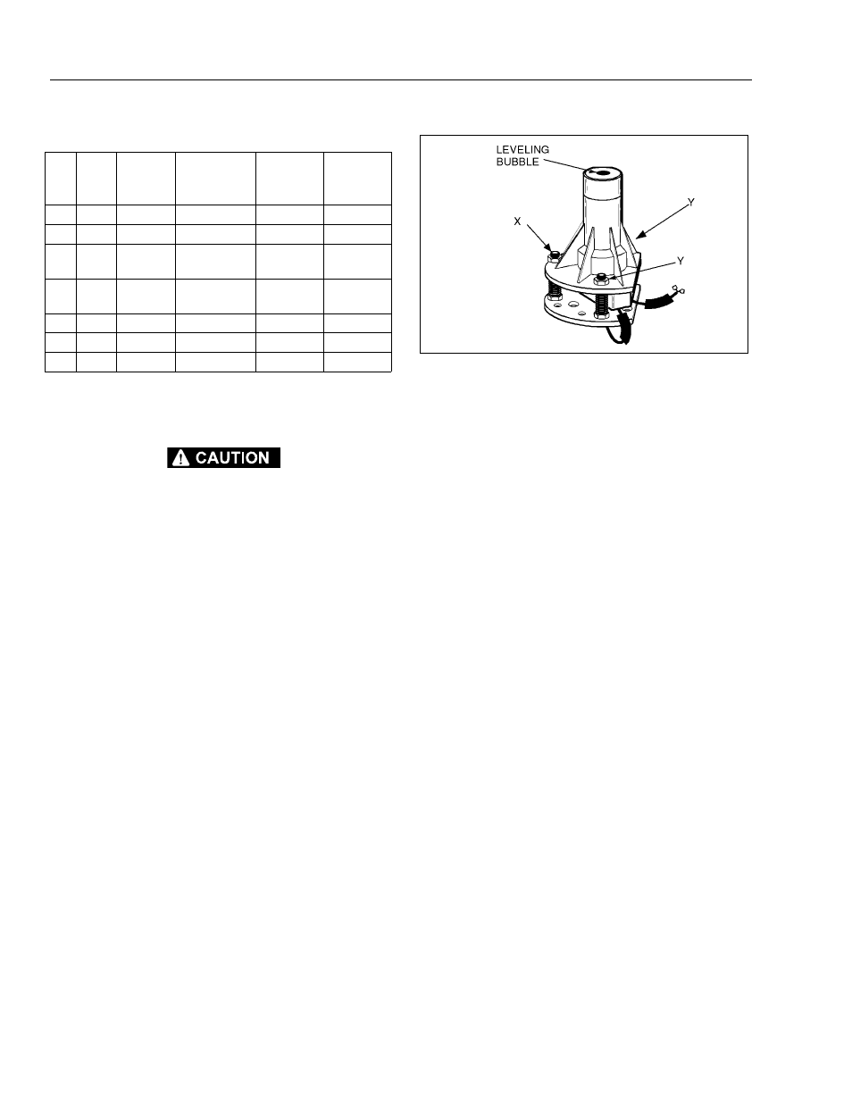
2. Level the base of the indicator by tightening the
three flange nuts through approximately one quarter
of its spring travel. DO NOT ADJUST THE “X” NUT
DURING THE REMAINDER OF THE PROCEDURE.
3. With the electrical connections complete, using bub-
ble level on top of indicator, slowly tighten or loosen
the three flange nuts until indicator is level.
4. Individually push down on one corner at a time;
there should be enough travel to cause the switch to
trip. If the switch does not trip in all three tests, the
flange nuts have been tightened too far. Loosen the
“X” nut and repeat steps (2) through (4) LIMIT
SWITCHES ADJUSTMENTS.
3.21 SPARK ARRESTER CLEANING
INSTRUCTIONS
1. Remove the cleanout plug in the bottom of spark
arrester (muffler).
2. Without causing deformation (or any type of dam-
age to the spark arrester) repeatedly tap on the
arrester near the cleanout plug. This may be enough
to begin drainage of the spark trap.
3. An industrial vacuum cleaner can do a complete job
at this point.
a. Or, IN A SAFE AREA, start the engine. Then
alternate between low idle and high idle for two
to three minutes.
b. Or, operate the engine as required by the appli-
cation for two to three minutes.
4. Install the cleanout plug.
Table 3-9. Coupling Port Information Table
Port
No.
Outlets
Port Size
Description
Operating
Pressure
PSI (Bar)
Proof
Pressure
PSI (Bar)
1
2
-6
Brake
450 (31)
675 (46.5)
2
2
-6
2 Speed
4500 (310) 6750 (465)
3
1
-6
Steer
2500 (138)
3750
(258.5)
4
1
-6
Steer
2500 (172)
3750
(258.5)
5
3
2-16, 1-6
Drive Reverse
4500 (310) 6750 (465)
6
1
-16
Drive Forward
4500 (310) 6750 (465)
7
2
-12
Drain
250 (17)
375 (26)
Figure 3-50. Tilt Switch Adjustment.