Advance Adapters 477023 User Manual
Page 10
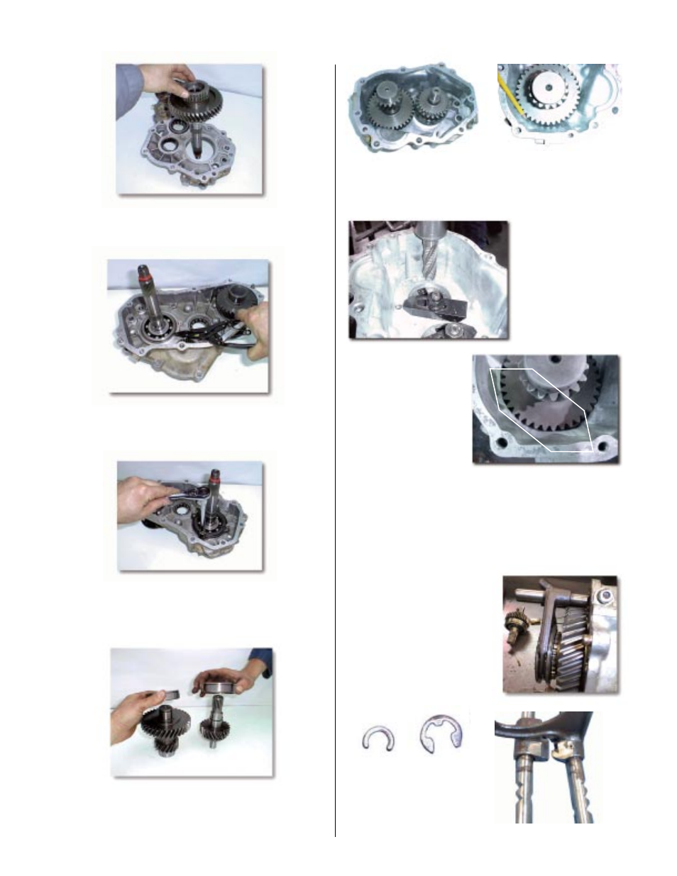
(Step A-12)
(12) If your case uses the large E-clip, remove and replace with
the new C-clip (supplied in kit).
See Photo A-12a
. The shift
fork/rail assembly should be test fit before proceeding with
the assembly. Some grinding on the fork rail boss may be
required to clear the larger gear. See
Photo A-12b
for
grinding locations.
As a final check, reinstall shift
rails/fork assembly over new
gear and temporarily install
mating case so that the shift
rails are indexed into the case.
The gear should rotate easily
with no interference. Now re-
move case half and go on to
Step 13.
Photo A-12a
Photo A-12b
r
New style
C-clip
supplied.
r
Discard this
E-clip.
(Step A-7)
(7) Install the output shaft assembly into the case. You might
have to tap it in gently with a soft plactic hammer.
(Step A-8)
(8) Install a new snap ring (provided in the kit) that holds in the
bearing for the output shaft.
(Step A-9)
(9) Install the bearing retainer into its original position. Apply
Loctite 242 and install the 4 bolts removed earlier. Torque
evenly to 13 ft./lbs.
(Step A-10)
(10) Press on the cluster / counter gear and input gear bearings.
Be sure to install new snap rings that retain the bearings
on the shafts.
(Step A-11)
(11) Install the cluster and input gears into the reduction case.
A slight tap from a soft plastic hammer should be all it takes to
get them seated. Note: On the 4.77 & 5.0 gears, the case must
be machined to provide
clearance for the clus-
ter gear. On some 4.0
cluster gears, we have
found that the case will
need to be relieved due
to core shift. Spin the
cluster gear to check for
interference.
4.77 cluster interference
You can grind the necessary
clearance; however, it is rec-
ommended to machine the
case for this clearance. We
used a 1” coarse pitch
roughing end mill and took
approximately .050” off the
inside case wall. (We also
offer a new front housing that
has the proper gear clear-
ance,
P/N 51-5911
)