Aerovent ES-2-06 User Manual
Page 5
Twin City Fan Companies Engineering Supplement 2-06
5
10. Mount drives as follows:
a. Slip (do not pound) proper sheave onto cor-
responding shaft. CAUTION: PLACING FAN
SHEAVE ON MOTOR CAN OVERSPEED WHEEL
AND CAUSE STRUCTURAL FAILURE.
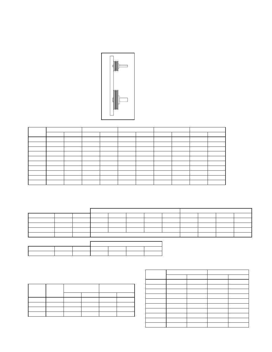
b. Align sheaves with a straight-
edge extended along the
perimeters of both sheaves,
just making contact in two
places on outside perimeters
of both sheaves (see Figure
5). Parallel alignment should
be within 5mm per meter
of center distance. Angular
Misalignment should be less
than 1 degree.
c. Tighten down sheave bolts.
d. Install a matched set of
belts. Adjust belt tension as
indicated in “Drive Mounting”
step #3.
Size
Grade 2
Grade 5
Grade 8
Aluminum
Stainless
(Ft - lbs)
(N - m)
(Ft - lbs)
(N - m)
(Ft - lbs)
(N - m)
(Ft - lbs)
(N - m)
(Ft - lbs)
(N - m)
1/4 - 20
5.5
7.5
8
10.8
12
16.3
3.8
5.2
6.3
8.5
5/16 - 18
11
15
17
23
25
34
6.7
9.1
11
15
3/8 - 16
22
30
30
41
45
61
11.9
16
19
26
7/16 - 14
30
41
50
68
70
95
19
26
31
42
1/2 - 13
55
75
75
102
110
149
26
35
43
58
5/8 - 11
100
136
150
203
220
298
59
80
92
125
3/4 - 10
170
230
270
366
380
515
81
110
128
174
7/8 - 9
165
224
430
583
600
813
125
169
194
263
1 - 8
250
339
645
874
900
1220
184
249
287
389
1 1/4 - 7
500
678
1120
1518
1500
2034
336
456
523
709
e. Tighten belts to proper belt tension. Record the
belt tension used. See drive mounting section for
tensioning instructions. Proper tension is specified
in the datasheet included with the fan.
11. Fans that have motors and drives mounted at the
factory are trim balanced prior to shipment. This
is not possible on units that are shipped without
motors and drives. The addition of drive compo-
nents in the field can create unbalance forces. Twin
City Companies, Ltd. recommends final balancing
of the unit after the drive components are installed.
Failure to do so voids the Twin City Fan Companies,
Ltd. warranty.
12. Repeat the installation checks indicated for factory
assembled units to assure proper tightness and
alignment of all components.
Bearing Installation
Bearings are only to be field installed when accompa-
nied by installation instructions from the bearing manu-
facturer. When field installation is required, follow the
manufactures instructions carefully to install bearings.
Table 1. Bolt Tightening Torque
METRIC SHAFTS
SET SCREW SIZE
LOCKING COLAR SCREW SIZE
Manufacturer
BRG ID
Units
M5
M6
M8
M10
M12
M4
M5
M6
M8
Dodge
S2000
N-m
-
-
17.8
35
57
-
-
-
-
Dodge
SCAH
N-m
3.4
6.9
16
28
51
5.85
10.75
20.5
45
Dodge
SCMAH
N-m
3.4
6.9
16
28
51
5.85
10.75
20.5
45
SKF
SY
N-m
See Below
4.2
7.4
Table 2b. Metric Set Screw Torque Specifications
BEARING DIAMETER
Manufacturer
BRG ID
Units
12-35mm 40-45mm 50-65mm
70-100mm
SKF
SY
N-m
4
6.5
16.5
28.5
Table 2a. Bearing Cap Bolt Torque Specifications (see page 6)
Bolt
Size
Bushing
Type
Iron/Steel Hub,
Sheave
Aluminum
Hub
Ft - lbs
N - m
Ft - lbs
N - m
1/4 - 20
H
8
11
8
11
5/16 - 18
P, B
17
23
13
18
3/8 - 16
Q, R
30
41
24
33
1/2 - 13
S
70
95
-
-
Table 3. Browning Split Taper Bushing Tightening Torque
Table 2c. IP Set Screw Torque Specifications (see page 7)
Set Screw
Size
Steel Set Screws
Stainless Set Screws
Ft - lbs
N - m
Ft - lbs
N - m
1/4 - 20
5.5
7.5
5.8
7.9
5/16 - 18
11
15
11
15
3/8 - 16
22
30
19
26
7/16 - 14
30
41
28
38
1/2 - 13
55
75
42
57
5/8 - 11
100
136
82
111
3/4 - 10
170
230
115
156
7/8 - 9
165
224
-
-
1 - 8
250
339
-
-
1 1/4 - 7
500
678
-
-
Table 4. Set Screw Tightening Torque (other than bearing set screws)
Figure 5.
Sheave Alignment