Aerovent ES-2-06 User Manual
Page 12
12
Twin City Fan Companies Engineering Supplement 2-06
Operation Checklist
M
Verify that proper safety precautions have been followed.
M Electrical power must be locked off.
Check fan mechanism components:
M Nuts, bolts, setscrews are tight per Tables 1 - 4.
M
Mounting connections are properly made and tightened.
M Bearings are properly lubricated.
M
Wheel, drives and fan surfaces are clean and tightened.
M Rotating assembly turns freely and does not rub.
M Drives on correct shafts, properly aligned, and prop-
erly tensioned.
M Check that no foreign objects are in the fan or
ductwork.
Check fan electrical components:
M Motor is wired for proper supply voltage.
M
Motor was properly sized for power of rotating assembly.
M Motor is properly grounded.
M All leads are properly insulated.
M Resistance between motor windings and earth is over
10 megohms (see motor maintenance section).
M Control equipment is functioning properly.
Trial “bump”:
M Turn on power just long enough to start assembly
rotating.
M Check rotation for agreement with rotation arrow.
M Listen for any unusual noise.
Run unit up to speed:
M Bearing temperatures are acceptable (<200°F, 93°C)
after one to two hours of operation.
M Check for excess levels of vibration. Filter in readings
should be 7.2 mm/s RMS or less.
M Check that motor current draw is not above the
nameplate value.
After one week of operation:
M Check all nuts, bolts and setscrews and tighten if
necessary.
M Readjust drive tension if necessary. (See Table 5 for
drive maintenance schedule.)
Optional Accessories
1.
Turning Gear — A turning gear is sometimes used
in high temperature applications where the fan is
exposed to high temperature gases while not operat-
ing. The wheel and shaft can expand unevenly due
to the temperature when sitting idle, which can cause
vibration at startup and/or a permanent set to the
rotor. The turning gear slowly turns the fan from the
outboard side while it is not operating, providing for
even thermal expansion. It starts automatically when
the fan shuts down and disengages automatically
when the fan starts up again. More specific informa-
tion will be provided for each application.
2.
Shaft Seals — The standard shaft seal is a ceramic
fiber element retained with an aluminum retaining
plate and clips. Other configurations of shaft seals
are available for special applications, such as when it
is necessary to keep the shaft seal as gas tight as
possible. Shaft seal application manuals are provided
in Engineering Supplement ES-595.
3.
Variable Inlet Vanes — Variable inlet vanes are pro-
vided as assemblies internally in the inlet cone or
externally in a flanged cylinder. The vanes are used to
control volume and save power in installations where
different volumetric operating conditions are used.
Installation manuals are provided in other engineer-
ing supplements for specific fan types. Variable inlet
vanes may be provided with powered operators in
which case the manufacturer’s installation and operat-
ing manuals will be provided.
4.
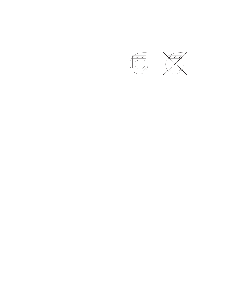
Inlet Box and Inlet Box Dampers — Inlet boxes may
be provided to allow transition from a duct to the
fan inlet. Inlet box dampers may also be provided for
volumetric regulation similar to inlet vanes. Dampers
are usually provided as a complete assembly and are
installed with the damper axles parallel to the fan
shaft. They should be installed to pre-spin the air in
the direction of fan rotation. See Figure 7.
5.
Outlet Dampers — Outlet dampers are usually provided
completely assembled like the inlet dampers. The damp-
er is bolted to the fan discharge for volume control.
6.
Shaft Cooler — Also referred to as “heat slingers”
or “cooling wheels,” these are small, radially bladed
aluminum wheels that are split and bolted for instal-
lation between the inboard bearing and fan housing.
The backplate usually is closest to the fan housing
and the blades face the bearing. Specific instructions
will be provided by application.
7.
Oil Circulating Systems — Usually the following modi-
fications will have to be made to the bearing if an
oil circulating system is used. When an oil circulat-
ing system is included, a manual for its installation,
operation, and maintenance will accompany it.
a. Four drain holes will be drilled in the bearing, two
on each side of the bearing. Because of this, the
bearing may be drained from either side. (Drain
from both holes on one side of the bearing.)
b. It is not necessary to drain the bearing.
c. The bearing will be packed with grease to prevent
corrosion until installed and started up. The drain
holes will be plugged with plastic covers to make sure
they are open.
The customer MUST REMOVE most
of the grease using solvent and remove the plastic
covers prior to starting the oil circulating system.
d. A wet sump will be added in case of circulating
oil pump failure. Seals will be provided to accom-
modate the resultant splashing.
e. The zerk on top of the bearing will be removed
for that hole to be used as the oil inlet.
Troubleshooting Guidelines
Use current safety practices when investigating fan or
system performance problems. General safe practices
and performance troubleshooting guidelines can be
found in AMCA Publications 410 and 202, respectively.
Fan application and field measurement procedures can
be found in AMCA Publications 201 and 203.
Below is a list of possible areas to check when air
or sound values do not match expectations. Most fan
problems can be pinpointed to one of these common
causes.
RIGHT
WRONG
Figure 7. Orientation of Damper Blades As Related to Fan Rotation