Aerovent ES-2-06 User Manual
Page 15
Twin City Fan Companies Engineering Supplement 2-06
15
5
4
3
Tool AS-14093
Blade Tip
Cheater Bar
Hub
Blade
Leading Edge
Detail "X"
Blade
Trailing Edge
Detail “X”
Vernier Index Line
(Blade As Shown
Is Adjusted To 35°
)
Figure 10. TCVX Blade Angle Adjustment
25.0"
5.0"
2.5"
5
4
3
Blade
Hub
6. Re-tighten the blade retaining bolts to the torque
shown in Table 7. Work in a star pattern, working your
way up to the desired torque in steps. Tightening one
bolt to the full torque before moving on to the next
can crack the hub.
Alternate Method
1. Loosen the blade retaining bolts until they are finger-
tight. At this point, the blades should rotate in their
sockets when grasped firmly and twisted, but not turn
on their own.
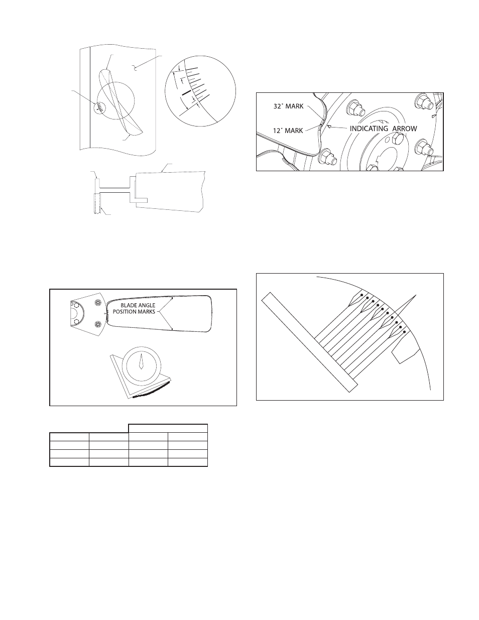
2. Angle setting marks on the blade line up with an indi-
cating arrow on the hub. There are two long marks
on the blade, one for 12° blade angle and another for
32°. Shorter indicating marks at 5° increments are in
between the two longer marks. See Figure 12.
Figure 11. Blade Position Marks
Blade Bolt Torque
Fan Size
Hub Size
Ft - lb
N - m
14 - 24
6
17
23
30 - 36
9
30
41
42 - 48
12
75
102
See Table 3 for bushing bolt torques - Use aluminum hub values.
Table 7. "E" Prop Torque Specifications
3. Twist each blade to the desired blade angle.
4. Re-tighten the blade retaining bolts to the torque
shown in Table 7. Work in a star pattern, working your
way up to the desired torque in steps. Tightening one
bolt to the full torque before moving on to the next
can crack the hub.
Blade Adjustment on Axiad Adjustable Pitch
Propeller
Each blade has cast into it a number of raised marks
with grooves in between and the fairing has a register
mark machined into it at each blade opening. See Figure
13, which identifies each of the ridges and grooves with
a number from 0 to 9. These numbers correspond to the
performance curve numbers shown in the AXIAD II design
performance manual.
On Arrangement 4 Type 3 Axiad fans, the blade angle
can be adjusted by removing the inlet screen. On ducted
fans, the case is provided with an 8-inch square door
in the fan tube. To set the blade pitch, proceed as fol-
lows:
NOTE: A 5/16” key with a square drive adaptor fitted to
a torque wrench is required. In most cases, a universal
joint will also be needed.
1. After access has been obtained to the rotor, loosen the
two blade bolts until the blade is free to rotate.
2. Rotate the blade to line up the register mark on
the fairing with the desired blade angle mark on the
blade.
CAUTION: Do not exceed blade position 9.
3. Tighten the two bolts evenly until a torque level of 65
ft-lb (88 N-m) is reached.
CAUTION: It is important that the blade bolts are
torqued to the specified value. Do not hand-tighten the
bolts.
Figure 13. Axiad Blade Angle Indicators
INDEX ON
HUB
BL
AD
E
PO
SIT
IO
NS
9
8
7
6
5
4
3
2
1
0
Figure 12. "E" Prop Blade Angle Indicating Marks