Aerovent ES-2-06 User Manual
Page 13
Twin City Fan Companies Engineering Supplement 2-06
13
Air Capacity Problems
1. Resistance of the system is not at design rating. If
resistance is lower than expected, both airflow and
horsepower may be up. If resistance is higher than
anticipated, air volume will be down.
2. Fan speed is not at design speed.
3. Air density is not at the design value. Also check air
performance measurement techniques/procedures.
4. Devices for air modulation are closed or plugged.
Also check filters.
5. Wheel mounted improperly or is rotating in reverse.
6. Parts of the system or fan have been damaged or
need cleaning.
Noise Problems
1. Air performance is incorrect and the fan is not at
design point of operation. Fan is being forced to
operate in an unstable flow region.
2. Bearing failure. Check bearings (lubrication).
3. Supply voltage high or inconsistent supply frequency.
Adjustable frequency controllers can generate motor
noise.
4. Objects that are installed in a high velocity airstream
can generate noise. This includes flow sensors, turn-
ing vanes, etc.
5. Poor fan inlet conditions.
6. Acoustics or sound measurement procedure incorrect.
Vibration Problems
1. Misalignment of drive components.
2. Poor foundation or mounting structure (resonances).
3. Foreign material attached to rotating components.
4. Damaged rotating components (bearings, shaft, fan,
wheel, sheaves).
5. Broken, loose or missing setscrews.
6. Loose bolts.
7. Vibration transmitted by another source.
8. Water accumulating in airfoil blades.
9. Fan is operating in stall or unstable flow region.
Motor Problems
1. Incorrect wiring.
2. Speed of fan too high.
3. Parts improperly installed; binding.
4. Bearings improperly lubricated.
5. WR
2
capability of motor too low for application.
6. Protection devices may be improperly sized.
Drive Problems
1. Belts improperly tensioned.
2. Drive alignment is poor.
Disposal
All metal and other recyclable materials should be
separated and properly recycled. Paint, insulation, plastic,
packaging materials, lubricants, electrical components
and other items should be disposed of per local
regulations.
Handling
Roof ventilators should be lifted by using straps around
the fan housing or base only. Spreader bars should also
be used to avoid damage to stack caps or hoods. DO
NOT LIFT ROOF VENTILATORS BY THE STACK CAP
OR HOOD. On hooded units, disassemble the stack
from hood when lifting. Upblast models may be lifted
assembled.
Installation Instructions – Follow the above section
titled “Fan Installation, Factory Assembled Units” with
the exception of the instructions below for commercial
ventilators.
Roof ventilators should always be mounted to a flat,
level, solid and rigid structure. Particular caution should
be exercised when installing fans on metal buildings. Be
sure wall or roof is capable of supporting the fan(s). Fans
mounted on walls or roofs and not supported correctly
will cause vibration that could cause damage or injury.
Fans mounted off ground level should be rigidly
mounted to a structural platform and be placed over or
as near as possible to a solid wall or column.
Support for suspended fans must be cross-braced for
live load support to prevent side sway. Use guy wires
to help secure roof units if excessively windy conditions
prevail.
Appendix A – Commercial Ventilator Installation instructions
When the roof ventilator is designed to be mounted
on a curb, the curb should be securely installed prior to
the fan installation.
A damper, if used, should be securely mounted within
the curb or wall in a manner which allows free and
unobstructed operation.
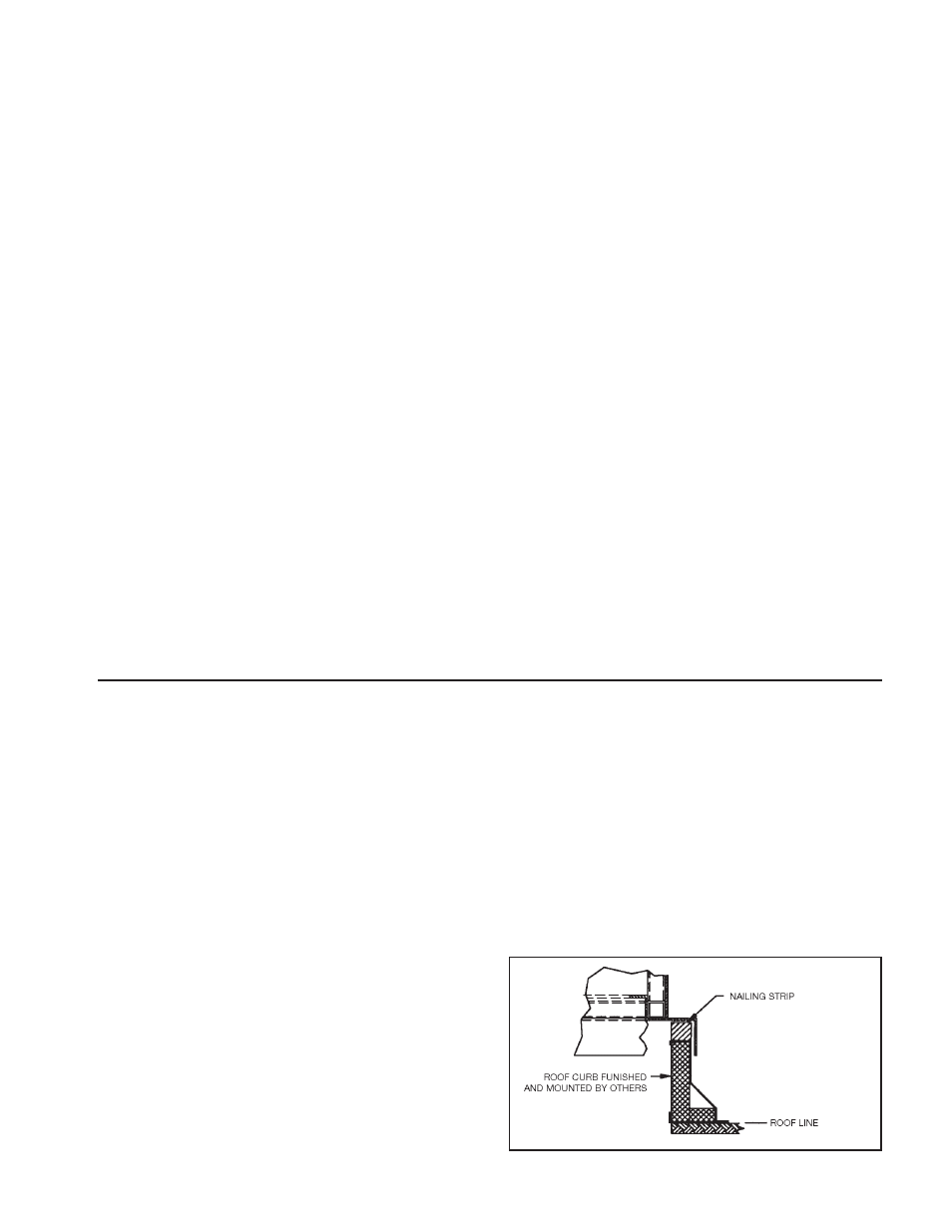
On roof units, anchor the fan securely to the curb.
Anchoring through the vertical portion of the curb cap
flange is recommended. Use a minimum of four lag bolts
or other suitable fasteners. See Fig 8 below.
Figure 8. Mounting Roof Ventilator to Curb Cap