Appendix b – axial fans – Aerovent ES-2-06 User Manual
Page 14
14
Twin City Fan Companies Engineering Supplement 2-06
Axial Fans - Securing the Wheel to the Shaft
If the propeller is removed for any reason, make sure that
it is securely attached to the shaft before restarting the
fan. If the propeller is attached to the shaft by means of
a Trantorque bushing, use the tightening torque values
shown in Table 6 below. For other bushings, see table 3
for proper torque values.
Axial Fans with Adjustable Blade Angles
The blades are set at the factory to the blade angle that
gives the performance specified on the order. This angle
should be checked prior to start-up. The blade angle
should not be changed from that stated for the order
without assuring that a change in blade angle will not
overload the motor, any controls, or other items. Vibration
levels shall also be checked in accordance with ISO
14694:2003, “Industrial Fans – Specifications for Balance
Quality and Vibration Levels” if any change is made to
blade angles.
Appendix B – Axial Fans
Blade Adjustment on Adjustable Pitch Vaneaxial
Type TCVX
The patented wheel construction uses friction and cen-
trifugal force to hold the blades in place. No disassembly
of the wheel is required to change the blade angles. If
it is necessary to change the blade angle, the following
procedure should be used:
1. Work safely. Make sure that proper safety precautions
have been followed. Electrical power must be locked
off.
2. The adjustment can be made through the inlet on open
inlet fans. On fans with ducted inlets, open the wheel
area access door.
3. Place adjustment tool around end of blade (see Figure
10). If necessary, apply “cheater bar” around the 11/4"
(31.75mm) diameter end for additional leverage. The
blades can be turned by hand on open inlet fans. If
additional leverage is needed, place a wrench on the
leading edge of the blade near the hub. Take care not
to mar the surface of the blade.
Blade Adjustment on Type "E" Adjustable Pitch
Propeller
Preferred Method (more Accurate)
1. Lay the hub on a horizontal surface with the concave
(air leaving) surfaces of the blades facing upwards.
2. Loosen the blade retaining bolts until they are finger-
tight. At this point, the blades should rotate in their
sockets when grasped firmly and twisted, but not turn
on their own.
3. Place an angle meter across the two blade angle posi-
tion marks on a blade. See Figure 11.
4. Twist the blade to the desired blade angle.
5. Repeat steps 3 and 4 for the remaining blades.
Trantorque
Size
Shaft
Diameter
Socket
Size
Torque
Ft-Lb
N-m
7/8
7/8
1-1/2
71
96
1-1/8
1-1/8
1-3/4
130
176
1-3/8
1-3/8
2
141
191
1-5/8
1-5/8
2-1/4
233
316
1-7/8
1-7/8
2-1/2
325
441
2-1/8
2-1/8
2-3/4
440
597
2-3/8
2-3/8
3
470
637
2-7/8
2-7/8
3-1/2
550
746
Table 6. Trantorque Bushing Torque Values
Note: These torque values are to be obtained with a calibrated
torque wrench. DO NOT apply any lubricant to any part of the
Trantorque
®
hub. DO NOT use an anaerobic thread adhesive
such as Loctite
®
on the threads.
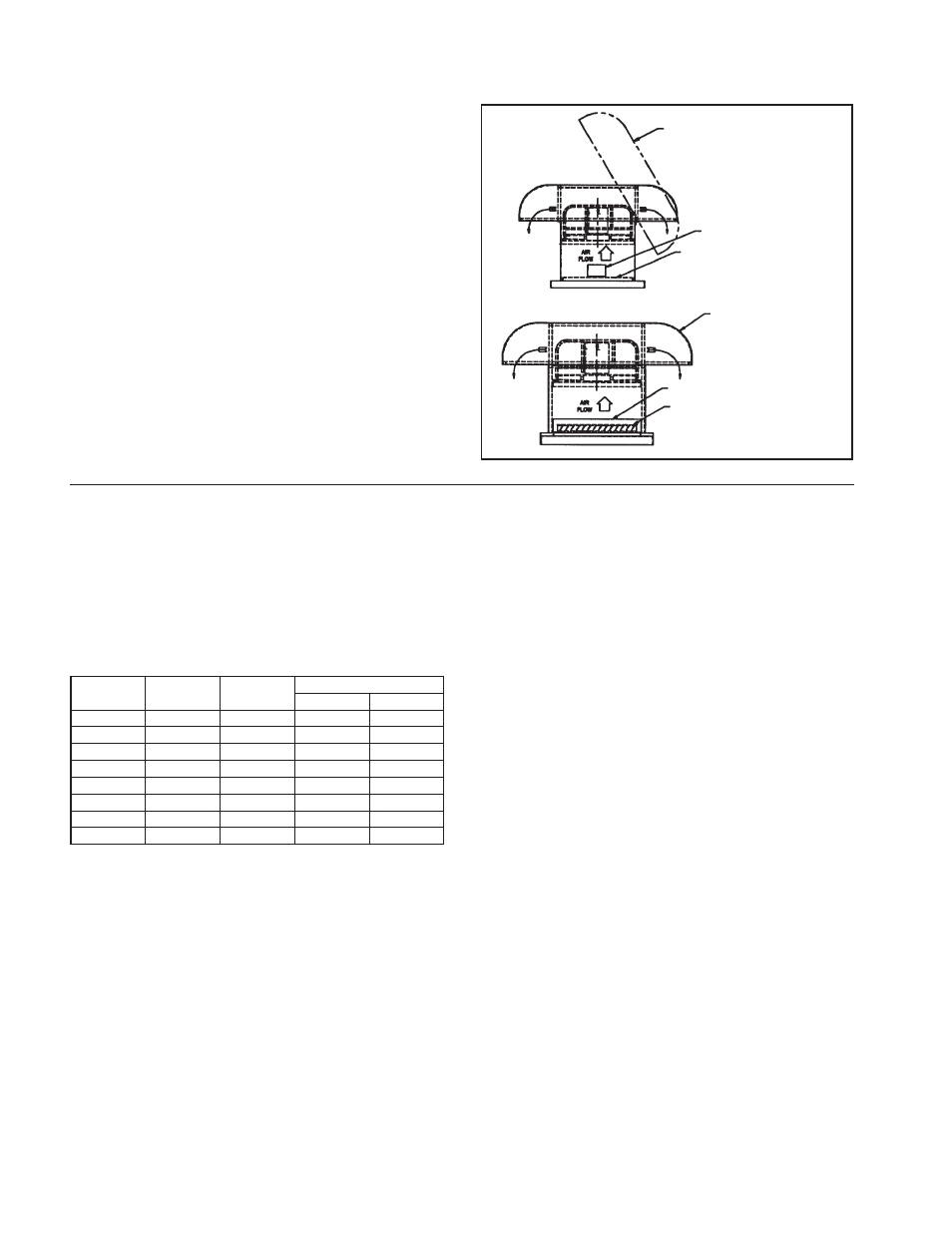
Figure 9. Typical Hooded Roof Ventilator Installations
HINGED HOOD
BOLTED HOOD
SIZE 12" – 42" ACCESS
DOOR FOR INSPECTION
SIZE 48" – 60"
ACCESS DOOR FOR DAMPER
REMOVAL
SAFETY SCREEN STANDARD.
OPTIONAL DAMPER NOT SHOWN.
OPTIONAL DAMPER
Appendix A – Commercial Ventilator Installation instructions
(cont'd)
Hooded Ventilators
Hooded units sizes 12 to 42 use a one-piece hinged
hood. To lift the hood, remove the two bolts located
under the mushroom cap and prop the hood up with the
supplied safety rods. Push and lock into place. A screw
is installed at the end of the pin side of the hinge in the
hood angle to prevent accidental removal of the hood. To
close the hood, replace the bolts to lock in place. For
size 48, a one-piece bolted hood connects directly to the
fan stack. To lift the hood off the unit, remove the bolts
located under the mushroom cap. For sizes 54–72, a two-
piece bolted hood connects directly to the fan stack. To
lift the hood off the unit, remove the sheet metal bolts
than connect the right and left sides of the hood and
then remove the bolts located under the mushroom cap.
See Figure 9 below.