Aerovent ES-2-06 User Manual
Page 16
TM
®
4. Repeat steps 1 through 3 for all blades. Make sure all
blades are set at the same mark.
5. After all blades are set at a new angle, run the fan for
a few minutes and then re-torque all blade bolts.
Blade Adjustment on Aerovent Reversible
Adjustable Pitch Propeller
Assembly Procedures
1. Lay hub on a horizontal surface with openings of
shank sockets (Figure 15) facing up. This is normally
the discharge side of the assembly.
2. Lay blade shank in socket with discharge side of the
blade up. The discharge side of the blade is the side
with the angle setting mark. Line up the index mark on
the blade with the proper angle mark on the end of
the shank socket (Figures 14 and 15) on the underside
of assembly.
3. Place cap over blade shank with beveled end toward
center. Install U-bolts and elastic nut stops. Before
tightening lock nuts, pull the blade outward to set
the key against the keyway and check angle setting
(Figures 14 and 15).
4. Tighten elastic stop nuts evenly and torque to the fol-
lowing foot-pounds:
5. Check angle setting to be sure it has not changed
during assembly. If so, loosen lock nuts and reset
angle. Tighten nuts again to proper torque. Do not
over-tighten. Be sure to tighten U-bolts evenly.
Setting Angle with Protractor (optional)
Under most conditions, the preceding assembly proce-
dure using the index marks is of sufficient accuracy.
When greater accuracy is desired, use a level bubble
protractor. Before the final tightening of the nuts, set the
protractor on the angle setting mark. (The hub and blade
assembly must be level for accurate setting.)
Adjust the angle by tapping the shank end with a
mallet.
Tighten lock nuts to proper torque per Table 8. Again
check the angle setting. Rotate propeller to check angle
on each blade in the same location.
Propellers may be assembled so the cap side of the
hub is the inlet side (reverse bore). If blades do not have
the index mark on the discharge side, it is then necessary
to adjust the blade angle with a protractor.
The hub and blades are balanced separately. The
weight distribution throughout the length of the blade
varies slightly. Therefore, the balance is to a constant
moment and blades may be assembled at random even
though the weights are slightly different.
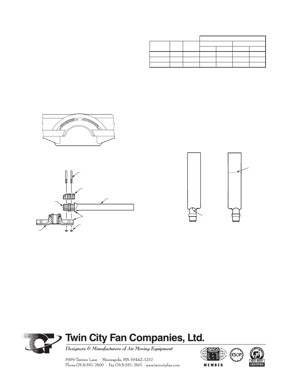
Angle setting index on shank socket. Marked
from 10° through 50°. Each mark is 2°.
Figure 14. Angle Setting Markings
Elastic Stop Nuts
Index Marks
Blade
U-Bolts
Cap
Blade
Shank
Hub
Figure 15. Assembly Exploded View
Angle
Setting
Mark
Index
Mark
Inlet Side
Discharge Side
Figure 16. Blades and Angle Setting Mark
Torque
Prop
Size
Hub
Size
U-Bolt
Size
Aluminum
Fiberglass
Ft-lb
N-m
Ft-lb
N-m
54 - 72
14
1/2”
20
27
30
41
81 - 96
18
3/4”
45
61
50
68
108 - 144
18
3/4”
45
61
50
68
Table 8. U-Bolt Torque for Aerovent Blades