Aerovent ES-2-06 User Manual
Page 3
Twin City Fan Companies Engineering Supplement 2-06
3
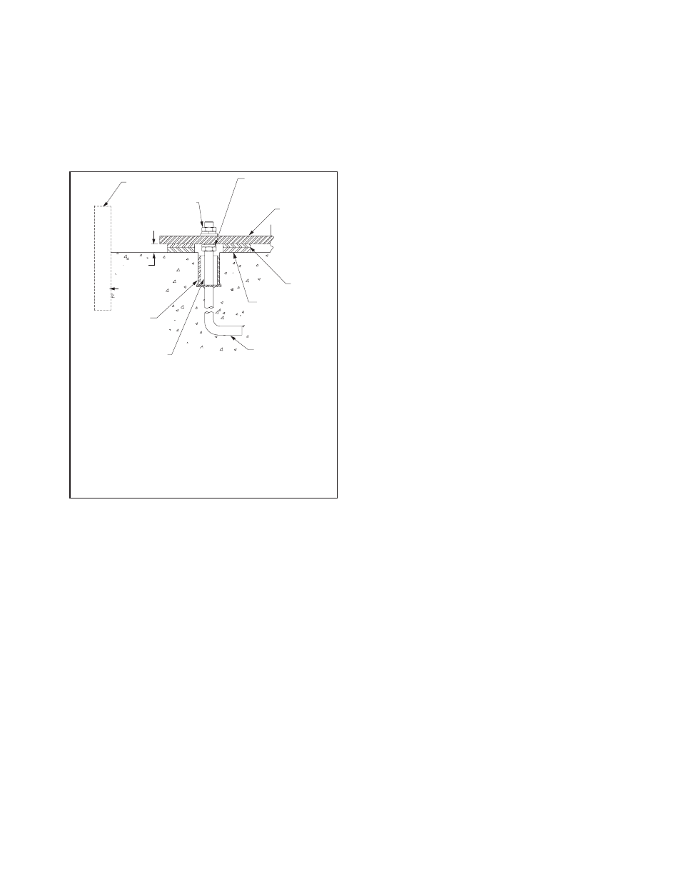
sleeve with a diameter of 2 to 21⁄2 times the anchor
bolt diameter should be provided around the anchor bolt
for final adjustment (see Figure 2). The mounting sur-
face of the foundation should be smooth for good shim
contact. When deciding the thickness of the foundation,
approximately 25 to 40mm height should be allowed for
shimming, grouting, leveling, washers, nuts, etc.
The foundation plan on the customer submittal draw-
ing indicates the mounting hole size and locations on
the fan.
If a structural steel base or platform is to be used,
the structure must be designed for the weight of the fan,
live loads imposed by rotation of the rotor and driver,
and any external live loads. The structure should be
designed to ensure that no natural frequency will occur
within 30% of the fan speed. This is especially true if
the structure supports more than one fan.
Any ducting should have independent support. Do
not use the fan to support ducting. The fan frame
can be designed to carry some external loads. Consult
the factory if this is a concern. Isolating the fan from
ductwork with flex connections eliminates transmission
of vibration. Fans handling hot gases require expansion
joints at both the inlet and discharge to prevent exces-
sive loads caused by thermal growth. Refer to AMCA
Publication 201 for good practices in ductwork geometry
and configuration. When possible, ductwork shall be
located where there is least risk of personnel tripping,
walking into or falling over the ductwork. If not possible,
warnings shall identify this hazard.
See Appendix A Commercial Ventilator Installation
Instructions for commercial ventilator foundation details.
Fans should not be located underneath other machin-
ery where there might be a risk of harmful liquid falling
onto fans from above.
Fans should be installed where they are readily acces-
sible to maintenance personnel, so that such personnel
are not required to stoop or crawl to access fans.
�
�
�
�
�
�
�
�
�
�
�
Figure 2. Typical Foundation Section
Fan Installation - Factory Assembled Units
General instructions for industrial centrifugal fans – For Axial
fans and commercial ventilators, follow steps below noting
instructions specific to those fan types in Appendix A and B.
Follow proper handling instructions as given earlier.
1. Move the fan to the final mounting position.
2. Remove skid, crates and packing materials carefully.
3. If vibration isolation is to be used, place isolation
base on mounting bolts. Line up holes in fan base
with bolts as indicated on the foundation plan of
the customer submittal drawing.
4. Consult each specific fan’s submittal drawing for
proper installation arrangement and mounting dimen-
sions. Place the fan on mounting structure. Carefully
level the unit (checking the level on the shaft) on
the foundation and shim as necessary using stain-
less steel shims on both sides of each anchor bolt.
Anchor bolts are to be pre-tensioned per Table 1.
For metric grade bolts or materials not shown in
Table 1, check with bolt manufacturer for the proper
torque. (See details specific to commercial ventila-
tors in appendix A for this step).
5. Check the alignment of the bearings. Shim or
reposition the bearings if necessary. In many split
housing roller bearings, the gap between the seal
carrier and housing can be measured with a feeler
gage. The variation in this gap should be less than
half of the maximum gap measured. In roller bear-
ings where this gap is not visible, alignment can
be verified by verifying the bearing is square with
the pedestal top. In ball bearings, the bearing outer
ring swivels in the housing to accommodate a small
amount of misalignment. Verify bearing set screws,
cap bolts, and collars are tightened per Tables 2a,
2b and 2c.
6. Check face alignment of sheaves on belt driven fans.
Parallel alignment should be within 5mm per meter of
center distance. Angular Misalignment should be less
than 1 degree. Check and record tension of belts
to see if it is sufficient. Proper belt tension is speci-
fied on the included datasheet. If belt tension needs
adjustment, instructions on belt tensioning are given
in the Drive Mounting section of this manual. Sheaves
on belt driven fans are often provided with taperlock
bushings. When tightening bushing bolts, proceed in a
progressive manner to avoid cocking the tapered sur-
faces between the bushing and the sheave. Bushing
bolt torque specifications are indicated in Table 3.
7. Check alignment of factory mounted couplings, as
they are subject to misalignment during shipment.
Realign if necessary in accordance with the instruc-
tions which are included with the shipment.
NOTE:
Most couplings need lubrication.
8. Make sure there is no rubbing or binding and that
the wheel-inlet cone or wheel to fan housing clear-
ances and overlap are correct. Overlap values or
other dimensions to verify proper wheel location are
given in the included documentation specific to the
fan. Wheel clearance should be verified to match
the specified value and be uniform. The measured
values should be recorded.
9. Check the tightness of the wheel on the shaft per
Table 4. The measured torque should be recorded.
10. Check the tightness of foundation bolts, motor
mounting bolts, and bearing mounting bolts per
Table 1. For metric bolts or grades not specified in
Table 1, check proper torque values per the bolt
manufacture.
NOTES:
¿
Temporary form for grout pouring.
¡
Hex nut, split ring lock washer and tapered or flat washer.
¬
1" to 1.5" grout allowance to be filled with nonshrinking machinery
grout.
√
Pipe-bolt sleeve diameter 2 to 2
1
/
2
times bolt diameter for correc-
tion of alignment errors.
ƒ
Care should be taken that anchor bolt sleeves are filled with
grout.
≈
J-Bolt leg should be fastened to foundation rebar.
≤
Shimming surface to be smooth, level, dressed if necessary.
«
Full width stainless steel shims.
»
Fan base angle or structural steel.
…
Leveling nut, if used, should be backed off after shimming for final
tightening of hex nuts.