Snorkel TB65J User Manual
Page 55
Chapter 8 – Operation
TB65J – 0084248
5
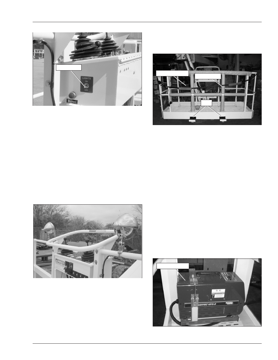
Figure 8.11 – Upper Controls
If the engine is running, the idle speed increases when
the driving lights are turned on.
Note
Working with the driving or platform work lights on, while
the engine is off, can discharge the batteries enough that
the engine will not start or the emergency power system
will not operate. If the engine cannot be left running while
the lights are on, start and run the engine for at least 15
minutes each hour.
Platform Work Lights
The optional platform work lights are located on the top rail
of the platform next to the upper controls (refer to Figure
8.2). The direction a light points can be adjusted by using
two
/
2
″
wrenches to loosen the clamp below the light.
Figure 8.12 – Upper Controls
The lights are operational when the machine is set up for
operation from the upper controls.
Glazier Package
The glazier package allows the platform operator to posi-
tion glass at the work place. Refer to the Glazier Package
manual (Snorkel Part Number 042269) for information
on proper use of the glazier package.
The package includes two lined trays with keeper pins,
platform rail padding, and tie-down straps with protectors
(refer to Figure 8.3).
Figure 8.13 – Glazier Package
Platform Capacity
The platform rated work load is the total weight of the per-
sonnel and equipment that may be lifted in the platform.
The work load is stated on the platform rating placard
mounted on the toeboard at the rear of the platform.
The maximum total load carried by the glazier trays must
not exceed 250 lb (3 kg). The weight of the load in
the trays reduces the platform capacity by the amount
of the load.
Platform Welder
The platform welder package allows the platform operator
to perform continuous duty stick and TIG welding from the
platform. Refer to the Platform Welder Package manual
(Snorkel Part Number 008399) for information on proper
operation of the welder package.
The package includes a Lincoln® V275-S welder mounted
in the platform (refer to Figure 8.4). Power is supplied to
the welder by a hydraulically driven generator mounted
on the turntable.
Figure 8.14 – Platform Welder
Light Switch
Tray
Tie-Down Straps
Rail Padding
Platform Welder