Caution – Snorkel TB65J User Manual
Page 54
Chapter 8 – Operation
50
TB65J – 0084248
The engine will run at high idle while the generator is
operating. The generator will continue to operate as long
as the engine is running and the switch is in the genera-
tor position.
Dual Fuel
The dual fuel switch is located on the front of the lower
control panel.
Before starting the engine, place the fuel switch in the
gasoline or the LPG position. Open the shut-off valve on
the LPG gas tank if using LPG. Always keep the LPG tank
shut-off valve closed when not using LPG.
To switch from gasoline to LPG with the engine run-
ning:
. Open the shut-off valve on the LPG tank.
2. Place the fuel switch in the LPG position.
To switch from LPG to gasoline with the engine run-
ning:
. Place the fuel switch in the gasoline position.
2. Close the shut-off valve on the LPG tank.
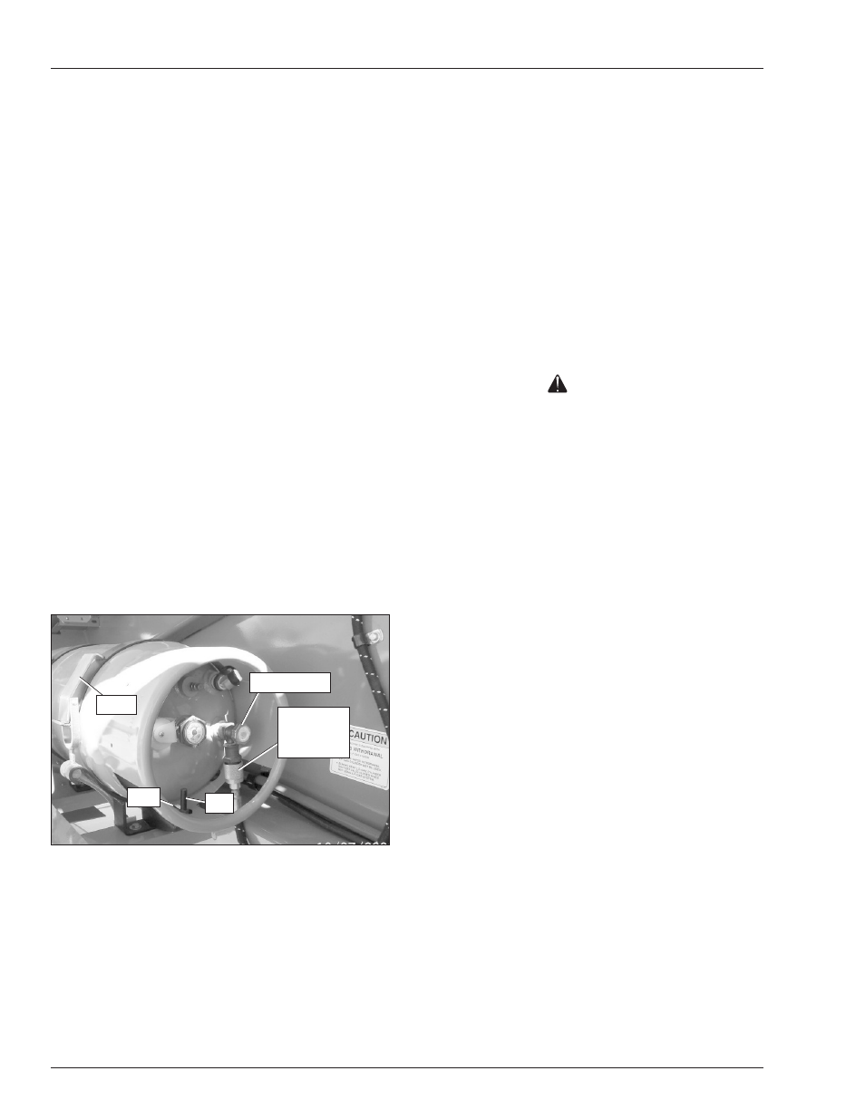
LP Fuel Tank
Use the following procedure to change the LPG tank.
. Close the shutoff valve (refer to Figure 8.0).
Figure 8.10 – LPG Tank
2. Remove the fuel line from the tank using the quick
disconnect fitting.
3. Pull on each latch to release the straps.
4. Carefully lift the tank from the cradle.
5. Place a full tank in the cradle making sure the slot in
the tank aligns with the pin.
6. Latch both straps to secure the tank.
7. Connect the fuel line and open the shutoff valve.
Air Line
The optional air line may be used to conduct air for tool
operation at the platform.
• The input connector is at the rear of the chassis and
the output connector is at the platform on the rotator
guard.
• The maximum working pressure of the line is 250 psi
(,723 kPa).
The air line may be used to conduct fluids such as water
or antifreeze. Contact Snorkel for compatibility information
before using the air line to conduct other fluids.
Caution
Fluid in the air line may damage some air tools or
freeze and damage the line. Drain and blow out the
air line after using it to conduct fluids.
Use the following procedure to drain the air line.
. Close the input connector on the rear of the turn-
table.
2. Open the output connector at the platform.
3. Raise the riser and main booms slightly above hori-
zontal.
4. Open the input connector on the turntable.
5. Allow the fluid to drain from the line.
6. Lower the boom and close both connections.
Driving Lights
The optional driving lights are for use in dimly lit areas and
are not intended for driving on public roadways. There are
two headlights at the front of the chassis and two blinking
taillights at the rear of the chassis.
The lights are operational when the machine is set up for
operation from the upper controls and the light switch is
turned on (refer to Figure 8.).
Latch
Shutoff Valve
Slot
Quick
Disconnect
Fitting
Pin