Danger, Warning, Caution – Snorkel TB65J User Manual
Page 32
Chapter 7 – Prestart Inspection
28
TB65J – 0084248
For optimal battery performance the battery fluid level
must be maintained and the battery connections must
be kept clean.
Battery Fluid Level
To inspect the battery fluid level:
. Remove the caps from the battery (refer to Figure 7.8).
2. Visually check the battery fluid level making sure the
level is within
/
4
″
(6 mm) of the bottom of the filler
neck inside each hole.
3. If necessary, add distilled water.
Note
Use only distilled water when refilling the battery. Tap
water may contain metallic solids such as iron which can
reduce the life of the battery.
4. Replace the caps on the battery. The caps must be
in place and tight during machine operation.
Battery Terminals
To inspect the battery terminals:
. Check the top of the battery, the terminals, and cable
ends. They should be clean and free of corrosion
(refer to Figure 7.8).
2. If necessary, clean the top of the battery. Clean the
terminals and cable ends with a wire brush or terminal
cleaning tool.
3. Make sure all cable ends are securely fastened to
the terminals.
Cables and Wiring Harness
To inspect the cables and wiring harnesses:
. Visually inspect all cables and wiring for wear and/or
physical damage such as loose connections, broken
wires, and frayed insulation.
2. Check the wiring in areas where a change in routing
direction may cause them to become pinched.
3. Make sure the cables and wires are properly routed
to avoid sharp edges, pinching, and scuffing.
Hydraulic System
Hydraulic power is supplied from an engine driven vari-
able displacement piston pump.
Danger
Hydraulic fluid escaping under pressure can have
enough force to inject fluid into the flesh. Serious
infection or reaction will result if medical treatment is
not given immediately. In case of injury by escaping
hydraulic fluid, seek medical attention at once.
Charging System
On machines with Cummins or Deutz engines, when
the engine is running, the ammeter needle (refer to
Figure 7.7) should be to the right of “0.” Left of the “0” is
discharging.
On machines with GM engines, when the engine is run-
ning, the voltmeter (refer to Figure 7.7) should indicate
between 2.5 and 4 volts.
Cold Weather Start Kit
If the machine is equipped with an optional engine block
heater or radiator hose in-line heater, visually inspect
the heater and power cord. Inspect for leaks around the
heater and for damage to the power cord.
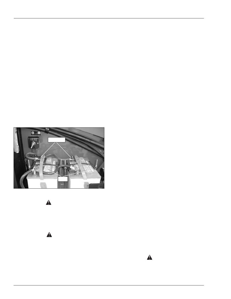
Electrical System
Electrical power is supplied from two 550 CCA, 2 volt
batteries. The batteries are behind the rear cowling door
on the left side of the machine (refer to Figure 7.8). The
battery supplies 2 volt DC electrical power to operate
the aerial platform electrical and electrohydraulic compo-
nents, including the emergency power system.
Figure 7.8 – Batteries
Warning
Batteries give off hydrogen and oxygen that can
combine explosively. Death or serious injury could
result from a chemical explosion. Do not smoke or
permit open flames or sparks when checking the
batteries.
Caution
Even with low voltage electrical systems, severe
arcing can occur. Electrical shock or component
damage may result from contact with energized
conductors. Use caution when working with any
electrical device.
The battery is automatically charged when the engine is
running. Include the battery when inspecting and servicing
the electrical system.
Caps
Terminals