Caution – Snorkel TB65J User Manual
Page 27
Chapter 6 – Controls
TB65J – 0084248
23
Boom Speed Knob
Use the boom speed control knob (refer to Figure 6.7) to
control the speed of the following boom functions:
• Main boom raise/lower
• Main boom extend/retract
• Turntable rotation clockwise/counterclockwise
Set the knob to slow (turtle) when beginning a boom
movement. The speed may be increased by slowly rotat-
ing the knob toward fast (rabbit). For smooth operation,
rotate the knob to slow when ending boom movement.
Engine/Emergency Power Switch
The engine/emergency power switch (refer to Figure 6.7)
is used to operate turntable, boom, and platform func-
tions using the emergency power system. The switch is
spring returned to the engine position for aerial platform
engine operation.
Caution
The emergency power system is for emergency low-
ering and stowing only. The length of time the pump
can be operated depends on the capacity of the bat-
tery. Do not use this system for normal operation.
• Hold the engine/emergency power switch downward
in the direction of the white arrow to activate the
emergency power system.
• Release the switch to disengage the emergency power
system.
If the engine is running, it will stop when the switch is
placed in the emergency power position.
Throttle Switch
The throttle switch is used to set the engine throttle speed
to either low or high idle.
Place the switch in the low position for normal machine
operation and in high to drive at maximum speed.
The engine has a three speed throttle operation from
the upper controls. Independent of the throttle switch,
the platform foot switch, when depressed, increases the
engine speed from low to mid-range.
High engine speed is obtained when the main boom is
stowed, the foot switch is depressed, the throttle switch
is in the high position, and the drive joystick is moved out
of neutral into the forward or reverse position.
The machine can be driven in mid-range engine speed
with the throttle switch placed in the low position.
Platform Foot Switch
The upper controls are interlocked through the platform
foot switch (refer to Figure 6.9).
Figure 6.9 – Platform
Step down on and hold the platform foot switch to activate
the drive and boom functions from the upper controls.
Horn Button
The button for the optional horn is on the right of the up-
per control panel (refer to Figure 6.0).
Press the button to sound the horn.
Figure 6.10 – Right Side of Upper Controls
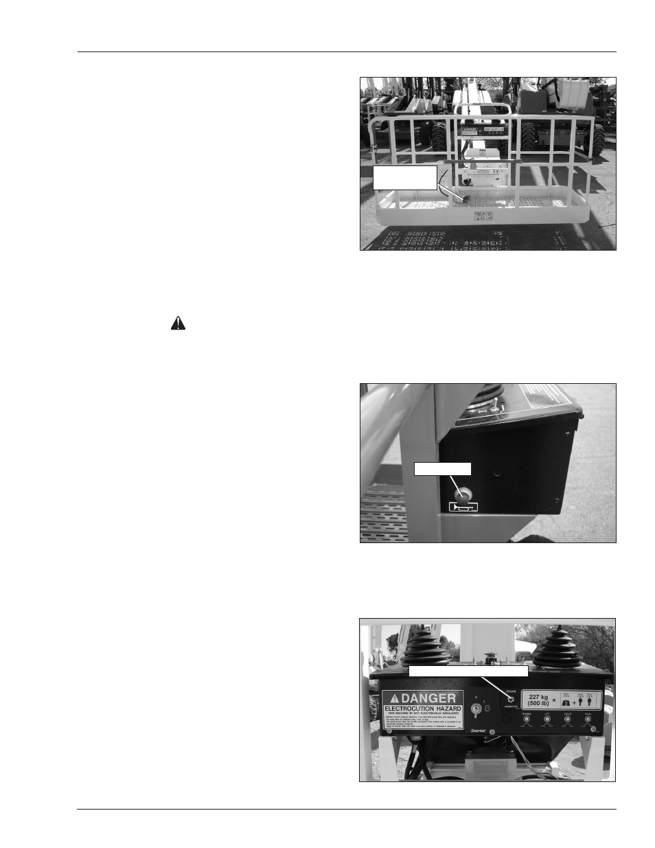
Machine/Generator Switch
The switch for the optional AC generator (refer to Figure
6.) is located on the front of the upper control panel.
Figure 6.11 – Upper Control Panel Front
Platform Foot
Switch
Horn Button
Machine/Generator Switch