Snorkel TB65J User Manual
Page 37
Chapter 7 – Prestart Inspection
TB65J – 0084248
33
Fasteners
To inspect the component fasteners:
. Visually inspect all fasteners to see that none are
missing or loose.
2. Inspect all of the bolts, nuts, rollpins, collars, and
snap rings that connect the booms and cylinders.
They should all be present, tight, and not damaged
in any way.
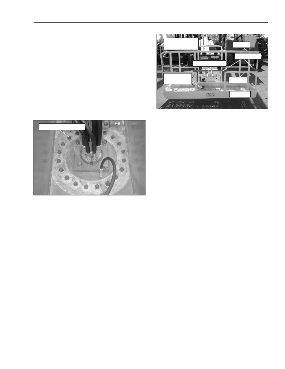
3. Raise the riser boom to access the inner race rotation
bearing bolts in the turntable (refer to Figure 7.9).
The outer race bolts can be viewed through the open-
ings in the turntable. Rotate the turntable to inspect
all of the outer race bolts.
Figure 7.19 – Inside Turntable
4. Inspect the inner and outer race rotation bearing
bolts to ensure that none are missing, damaged, or
loose.
Upper Control Station
Inspect the platform and upper controls, after verifying all
functions operated properly from the lower controls.
Guardrail System
The guardrail system includes (refer to Figure 7.20):
• A top rail
• A mid rail
• Gravity gate(s) and/or walk-through gate
• Toeboards around the sides of the platform.
Figure 7.20 – Guardrail System
To inspect the guardrail system:
. Visually inspect all components of the guardrail
system. Make sure the rails and toeboards are all in
place and free of any damage or deformation.
2. Visually inspect the rail and toeboard welds for
cracks.
3. Visually inspect all bolts and nuts fastening the plat-
form in place. They must be present and not show
any signs of looseness.
4. Inspect the gravity gates to be sure they are present,
are not damaged, and move freely.
5. Inspect the walk-through gate to see that it swings
freely, closes firmly, and is not deformed in any way.
Make sure the spring closes and secures the gate
when closed.
Lanyard Anchors
There are two lanyard anchors below the upper control
panel (refer to Figure 7.20).
To inspect the lanyard anchors:
. Visually inspect the lanyard anchors to make sure
they are in place and are not deformed.
2. Look for visible cracks in the welds and at the weld
to parent material joints. A bright light may be used
to provide adequate visibility of the inspection area.
Operating Controls
Use the following procedure to operate the machine from
the upper controls:
. Turn the battery disconnect switch on.
2. At the lower controls, place the emergency stop
switch and the start switch in the on position. Place
the controls switch in the upper control position.
Rotation Bearing Bolts
Toeboard
Platform Foot
Switch
Lanyard Anchors
Top Rail
Mid Rail
Walk-Through or
Gravity Gate
Gravity Gate