Danger, Warning, Chapter 11 – emergency operation – Snorkel S2633 User Manual
Page 47
S2633 – 8210048
43
If the main hydraulic system fails:
The aerial platform may be lowered using the emer-
gency lowering knob.
The machine may be towed if the drive system fails.
Refer to Emergency Lowering, or Towing for the ap-
propriate procedure.
Emergency Lowering Knob
Use the following procedure to lower the platform:
1. Retract the platform extension, if possible.
2. Locate the emergency lowering knob at the rear of
the chassis (refer to Figure 11.1).
Figure 11.1 – Rear of Machine
3. Make sure there is nothing in the way to obstruct the
platform when it lowers.
A
Danger
Pinch points exist on the moving components. Death
or serious injury will result from becoming trapped
between components. Make sure all personnel stand
clear while lowering the platform with the emergency
lowering knob.
4. Pull the knob outward to lower the platform. Release
the knob to stop.
A
Warning
The potential for an accident increases when safety
devices do not function properly. Death or serious
injury could result from such accidents. Fully close
the emergency lowering valve before operating the
aerial platform.
5. Make certain the knob is fully released and the emer-
gency lowering valve is fully closed before operating
the aerial platform.
y
y
y
Emergency
Lowering Knob
Emergency
Lowering Knob
Chapter 11 – Emergency Operation
Towing
The aerial platform may be pushed or pulled after disen-
gaging the brakes.
A
Warning
The aerial platform is free to move when the brakes
are disengaged. Death or serious injury could result.
Re-enable the brakes before operating the aerial
platform.
Use the following procedure to manually disengage the
brakes:
1. Chock the wheels to prevent uncontrolled motion of
the aerial platform.
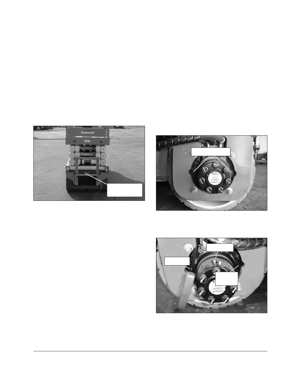
2. At the front drive motors, remove the thread protec-
tors from the outer plugs (refer to Figure 11.2).
Figure 11.2 – Front Drive Motor
3. Using a 5 mm Allen wrench, remove the outer plugs
turning counterclockwise (refer to Figure 11.3).
Figure 11.3 – Front Drive Motor
Turn the plugs alternately in ½ turn increments to
insure uniform adjustment and prevent binding.
y
Thread Protector
Thread Protector
Thread
Protector
Outer Plug
Inner Plug
Thread
Protector
Outer Plug
Inner Plug