Chapter 7 – controls, Danger – Snorkel S2633 User Manual
Page 21
S2633 – 8210048
17
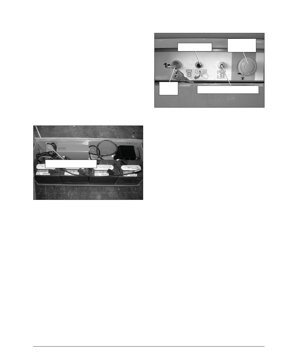
Figure 7.2 – Lower Controls
The following are located on the lower control panel:
Start switch
Emergency stop button
Enable button
Platform raise/lower switch
Start Switch
The start switch (refer to Figure 7.2) connects power to
all control circuits with a key switch.
Turn the switch to the on position to connect the elec-
trical power to the lower and upper controls.
When the machine is not in use, turn the switch to the
off position to preserve the battery charge.
Emergency Stop Button
The emergency stop (refer to Figure 7.2) is a two-position
red push button.
Push the button inward to disconnect power to all
control circuits.
Twist the button clockwise to restore power.
Both the lower and upper control emergency stop buttons
must be on to operate the machine.
Enable Button
The enable button (refer to Figure 7.2) must be pressed
when operating the platform raise or lower from the
lower controls. The button is spring returned to the off
position.
Hold the button inward continually to operate the
machine from the lower controls.
Platform Raise/Lower Switch
The platform raise/lower switch (refer to Figure 7.2) is
used to raise or lower the platform. The switch is spring
returned to the center off position.
y
y
y
y
y
y
y
y
y
Emergency
Stop Button
Enable Button
Start
Switch
Platform Raise/Lower Switch
Emergency
Stop Button
Enable Button
Start
Switch
Platform Raise/Lower Switch
Chapter 7 – Controls
A
Danger
Pinch points may exist between moving components.
Death or serious injury will result from becoming
trapped between components, buildings, structures,
or other obstacles. Make sure all personnel stand
clear while operating the aerial platform.
Controls to position the platform are located on the
lower control panel on the chassis and on the upper
control panel in the platform.
Controls to drive the aerial platform are located on the
upper control panel only.
Battery Disconnect
The battery disconnect plug is located inside the battery
tray (refer to Figure 7.1).
Figure 7.1 – Battery Tray
The battery disconnect removes electrical power from all
electrically controlled functions when it is unplugged.
Plug in the connector to electrically connect the bat-
teries to the electrical system.
Lower Controls
The lower controls (refer to Figure 7.2) are located on
the left side of the chassis. Only platform functions can
be operated from the lower controls.
y
y
y
Battery Disconnect Plug
Battery Disconnect Plug