Loaders, Pasando por una puerta, Battery charging (f igure 3) – Snorkel ULII40-sn15001-21372 User Manual
Page 12: Dc models, Loading, Bajando, Levantando
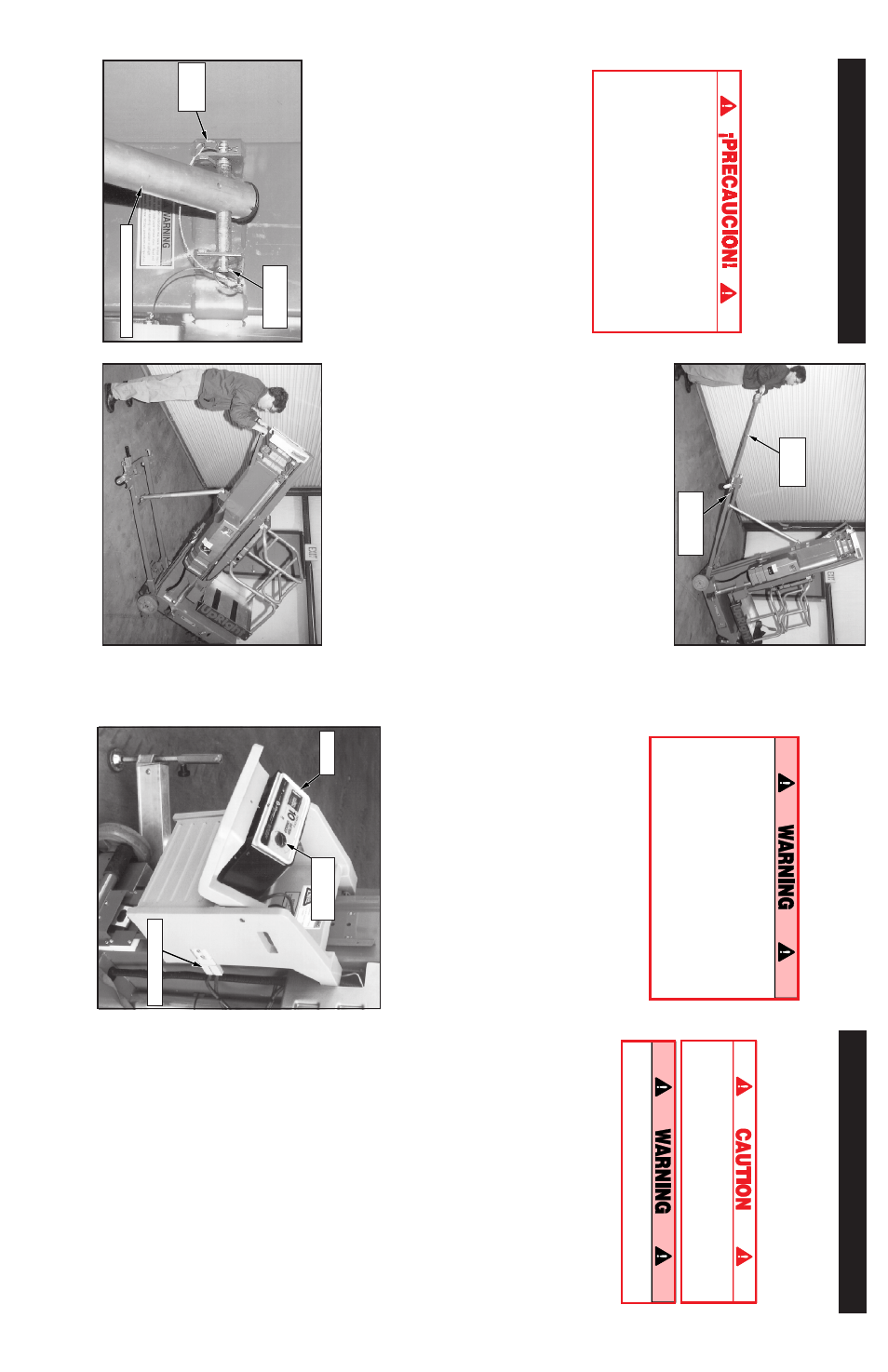
5
Figure
3:
Battery
Box
(DC
Models
only)
BATTERY CHARGING (F
igure
3)
Charge
batteries
at
end
of
each
work
shift
or
sooner
if
batteries
have
been
discharged.
Charge
battery
in
a
well
ventilated
area.
Do
not
charge
battery
when
the
work
platform
is
in
an
area
containing
sparks
or
flames.
Permanent
damage
to
battery
will
result
if
not
immediately
recharged
after
discharging.
Keep
charger
dry.
1.
Check
battery
fluid
level.
If
electrolyte
level
is
lower
than
3/8
in.
(10
mm)
above
plates
add
distilled
w
ater
only.
2.
Verify
charger
voltage
switch
is
set
to
12
volts.
3.
Connect
extension
cord
(12
ga.
(1.5
mm²)
conductor
minimum
and
50
ft.
(15
m)
in
length
maximum)
to
charger
plug.
Connect
extension
cord
to
properly
grounded
outlet
of
proper
voltage
and
frequency.
4.
Turn
charger
timer
knob
to
12.
Charger
amme-
ter
should
indicate
charge
rate.
5.
When
battery
is
fully
charged
turn
knob
to
OFF,
do
not
turn
knob
to
HOLD.
D
isconnect
extension
cord.
Battery
Box
Plug
Timer
Knob
Charger
Loaders
DC MODELS
Disconnect
the
plug
from
the
battery
box
and
remove
the
battery
box
from
the
rear
of
the
ma-
chine
(Figure
3).
The
battery
box
is
heavy,
52
lbs.
(23.6
kg),
lift
properly
(or
have
someone
help
you)
to
prevent
back
injury.
Make
sure
loader
fully
engages
tailgate
or
vehicle
bed.
LOADING
1.
Raise
the
loader
support
bracket
and
engage
the
retaining
pin
in
the
top
hole
of
the
loader
channel
(Figure
4).
2.
Secure
the
loader
to
the
loader
support
bracket
with
the
gravity
hook
(Figure
4).
3.
Position
the
unit
so
the
back
of
the
machine
comes
in
contact
w
ith
the
vehicle
bed
or
tail-
gate.
4.
Release
the
gravity
hook
and
slide
the
loader
down
until
it
comes
into
contact
with
the
vehicle
bed
or
tailgate
(Figure
4).
Then
reposi-
tion
the
loader
support
bracket
so
the
retaining
pin
is
in
the
first
available
hole
above
the
loader.
5.
Release
the
locking
pin
and
pull
the
T-handle
out
until
the
locking
pin
engages
the
hole
in
the
end
of
the
T-handle
(Figure
5).
6.
Lift
up
on
the
T-handle,
using
the
loader
as
a
pivot,
until
the
unit
rotates
to
a
horizontal
position
in
the
vehicle
bed
(Figure
6).
7.
Push
the
base
of
the
unit
towards
the
front
of
the
vehicle
bed.
The
machine
will
slide
on
the
loader
until
the
rear
wheels
are
on
the
bed.
The
unit
may
then
be
rolled
on
the
rear
wheels
and
upper
casters.
28
Pasando por una puerta
Los
modelos
UL32
y
UL40
están
provistos
de
un
marco-soporte
con
ruedas.
Al
voltear
la
unidad
hacia
atrás,
sobre
el
marco-soporte,
la
altura
se
reduce
permitiendo
que
la
unidad
pase
a
través
de
una
puerta
estándar.
BAJANDO
Antes
de
voltear
la
unidad
sobre
el
marco-
soporte
cerciórese
que
el
pasador
de
retención
y
su
pasador
horquilla
estén
bien
instalados
y
que
el
ensamble
del
cilindro
esté
totalmente
extendido.
NO
deje
caer
el
marco-soporte
No
se
pare
bajo
el
marco-soporte
ni
de
la
máquina
al
voltearla.
1.
Cerciórese
que
el
área
esté
libre
de
obstrucciones
y
personal.
2.
Sujete
el
marco-soporte
al
sacar
los
pasadores
horquilla
y
de
retención
(fig.
7)
3.
Baje
el
marco-soporte
hasta
que
el
ojo
del
ensamble
del
cilindro
esté
alineado
con
el
agujero
del
puntal
de
montaje
superior.
Enganche
el
cilindro
al
puntal
de
montaje
superior
insertando
el
pasador
de
retención
y
el
de
horquilla
(fig.
7).
4.
Para
extender
la
barra
de
volteo
a
la
posición
volteo/levante,
saque
el
pasador
de
enganche
y
tire
del
asa
del
ensamble
de
volteo
hasta
que
el
pasador
de
enganche
se
encaje
(fig.
8).
5.
Empuje
hacia
abajo
el
asa
de
la
barra
de
volteo
hasta
que
la
unidad
descanse
sobre
el
marco-
soporte.
A
medida
que
el
mástil
caiga,
sostenga
el
peso
empujando
hacia
arriba
el
asa
(fig.
8).
Con
ello
asegurará
que
la
máquina
se
apoye
suavemente
en
las
ruedas.
Figura
8:
B
ajando
y
levantando
con
la
barra
de
volteo
Figura
9:
C
omprimiendo
ensamble
del
cilindro
6.
Empuje
hacia
abajo
el
asa
de
detrás
del
mástil
para
comprimir
el
ensamble
del
cilindro
(fig.
9).
7.
Coloque
la
barra
de
volteo
en
la
posición
original,
aseguréndose
que
el
pasador
de
enganche
encaja
en
la
barra.
LEVANTANDO
1.
Tire
el
asa
del
mástil
para
estirar
el
ensamble
del
cilindro.
2.
Extienda
totalmente
la
barra
de
volteo
hasta
que
el
pasador
enganche.
3.
Levante
la
barra
de
volteo
por
el
asa.
A
medida
que
el
mástil
se
pare
sostenga
firme
la
barra
de
volteo
por
el
asa
(fig.
8)
mientras
baja
suavemente
la
máquina
sobre
las
ruedas.
4.
Coloque
la
barra
de
volteo
en
su
posición
normal
cerciorándose
que
el
pasador
enganche
la
barra.
5.
Sujetando
el
marco-soporte,
retire
el
pasador
de
retención
y
levante
el
marco-soporte
a
su
alojamiento.
Cerciórese
que
quede
asegurado
con
el
pasador
de
retención
y
el
pasador
horquilla
en
sus
lugares.
Figura
7:
Cilindro
conectado
con
pasador
de
retención
Pasador
de
retención
Pasador
horquilla
Ensamble
del
cilindro
Barra
de
volteo
Pasador
de
enganche