Passage through a doorway, Cargadores, Lowering – Snorkel ULII40-sn15001-21372 User Manual
Page 10: Raising, Modelos a corriente continua, Cargando, Cargando la batería (figura 3)
7
Passage Through A Doorway
The
UL32
and
UL40
are
equipped
with
a castered
rear
Tilt
Back
assembly.
W
hen
the
unit
is
tilted
back
onto
this
support
frame,
the
overall
height
is
reduced
to
allow
the
unit
to
pass
through
a
stan-
dard
doorway.
LOWERING
Before
tilting
the
machine
onto
the
rear
Tilt
Back
assembly
be
sure
the
retaining
pin
is
fully
inserted
with
the
hair
pin
retainer
installed
and
the
cylinder
assembly
is
fully
extended.
DO
NOT
drop
Tilt
Back
frame.
Keep
out
from
under
Tilt
Back
frame
and
machine
when
tilting.
1.
Be
sure
area
is
clear
of
personnel
and
obstructions.
2.
While
holding
Tilt
Back
frame,
remove
the
hair
pin
retainer
and
the
retaining
pin
(Figure
7).
3.
Lower
the
Tilt
Back
frame
until
the
hole
in
the
cylinder
assembly
aligns
with
the
upper
mounting
bracket
pin
hole.
Secure
the
cylinder
assembly
to
the
upper
mounting
bracket
using
retaining
pin
and
hair
pin
retainer
(Figure
7).
4.
Extend
Tilt
Back
Handle
to
the
tilt/lift
position
by
releasing
locking
pin
and
pulling
handle
out
of
the
Tilt
Back
assembly
until
the
locking
pin
engages
(Figure
8).
5.
Push
down
on
the
Tilt
Back
Handle
until
the
unit
comes
to
rest
on
the
Tilt
Back
frame.
A
s
the
mast
tilts
back,
counterbalance
the
machines
weight
by
increasing
upward
force
on
end
of
Tilt
Back
Handle
(F
ig
ur
e 8
).
This
allows
machine
to
gently
come
to
rest
on
Tilt
Back
casters.
Figure
7:
Cylinder
secured
w
ith
retaining
pin
Retaining Pin
Hair
Pin
Retainer
Cylinder
Assembly
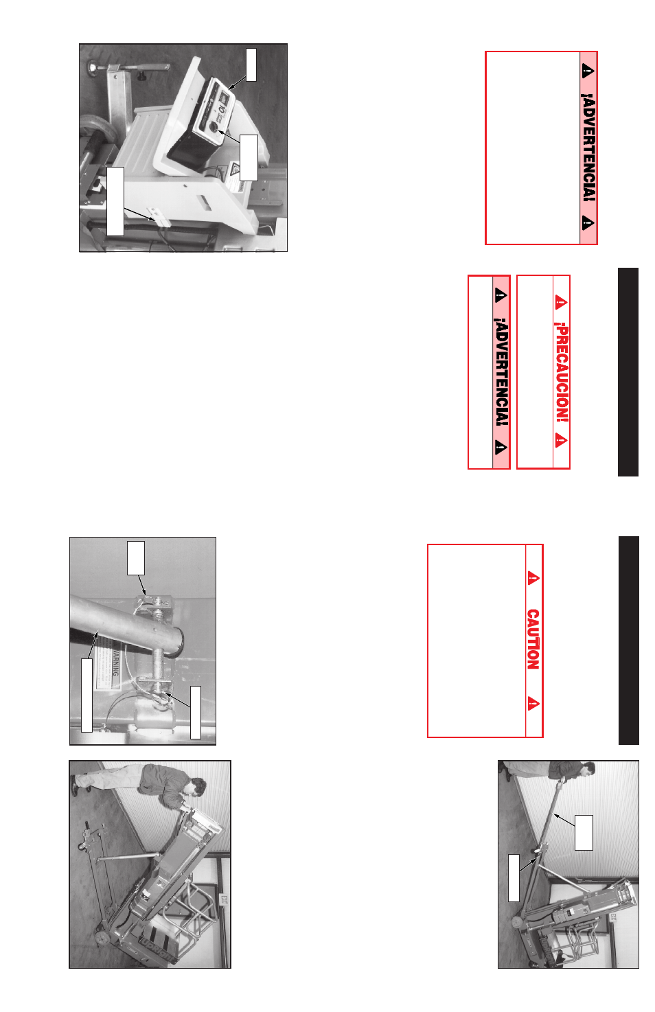
Figure
8:
Lowering
and
raising
w
ith
T
ilt
Back
Handle
Figure
9:
Compressing
cylinder
assembly
6.
Pull
down
on
the
handle
on
the
back
of
the
mast
to
compress
the
cylinder
assembly
(Figure
9)
.
7.
Return
Tilt
Back
Handle
to
storage
position
making
sure
locking
pin
engages
handle.
RAISING
1.
Lift
up
on
mast
handle
to
extend
cylinder
assembly.
2.
Fully
extend
the
Tilt
Back
Handle
until
the
locking
pin
engages.
3.
Lift
up
on
the
Tilt
Back
Handle.
As
the
m
ast
approaches
vertical,
counterbalance
machines
weight
by
increasing
the
downward
force
on
end
of
Tilt
Back
Handle
(Figure
8).
This
allows
machine
to
settle
gently
on
the
front
casters.
4.
Return
Tilt
Back
Handle
to
storage
position
making
sure
locking
pin
engages
handle.
5.
While
holding
Tilt
Back
frame,
remove
retain-
ing
pin
and
raise
Tilt
Back
assembly
to
the
stowed
position.
Secure
with
the
retaining
pin,
making
sure
pin
is
fully
inserted
and
hair
pin
retainer
installed.
Tilt
Back
Handle
Locking
Pin
26
Cargadores
MODELOS A CORRIENTE CONTINUA
Desconecte
el
enchufe
de
la
caja
de
la
batería
y
remueva
esta
caja
de
atrás
de
la
máquina
(fig.
3).
La
caja
de
la
batería
es
pesada,
23,60
kg
(52
lb),
levántela
correctamente
o
pida
ayuda
para
prevenir
lesiones
a
la
columna.
Cerciórese
que
el
cargador
cubre
la
puerta
trasera
o
la
cama
del
vehículo.
CARGANDO
1.
Levante
el
puntal
del
soporte
del
cargador
y
conecte
el
pasador
de
retención
al
hoyo
superior
del
canal
del
cargador
(fig.
4).
2.
Enganche
el
cargador
al
puntal
de
soporte
con
el
gancho
por
gravedad
(fig.
4).
3.
Coloque
la
máquina
de
modo
que
la
espalda
de
la
máquina
quede
en
contacto
con
la
cama
del
vehículo
o
la
puerta
trasera.
4.
Suelte
el
gancho
por
gravedad
y
deslice
el
cargador
hacia
abajo
hasta
que
toque
la
cama
del
vehículo
o
la
puerta
trasera
(fig.
4).
Luego
reubique
el
puntal
del
soporte
del
cargador
de
modo
que
el
pasador
de
retención
esta
en
el
primer
hoyo
disponible
sobre
el
cargador.
5.
Suelte
el
pasador
del
pasador
de
enganche
y
tire
la
manilla
T hasta
que
el
pasador
de
enganche
se
encaje
en
el
hoyo
del
final
de
la
manilla
T (fig.
5).
6.
Levante
la
manilla
T,
usando
el
cargador
como
pivote,
hasta
que
la
unidad
rote
a
una
posición
horizontal
en
la
cama
del
vehículo
(fig.
6).
7.
Empuje
la
base
de
la
unidad
hacia
el
frente
de
la
cama
del
vehículo.
La
máquina
se
deslizará
en
el
cargador
hasta
que
las
ruedas
traseras
estén
sobre
la
cama.
La
unidad
puede,
entonces,
empujarse
sobre
las
ruedas
traseras
y
las
ruedas
superiores.
CARGANDO LA BATERÍA (figura 3)
Cargue
la
batería
al
final
de
cada
turno
de
trabajo
o
antes
si
ha
sido
descargada.
Cargue
la
batería
en
un
área
bien
ventilada.
No
cargue
la
batería
cuando
la
plataforma
de
trabajo
esté
donde
se
produzcan
chispas
o
llamas.
La
batería
se
dañará
permanentemente
si
no
se
carga
inmediatamente
después
que
se
ha
descargado.
Mantenga
el
cargador
seco.
1.
Verifique
el
nivel
del
fluido.
Si
está
a
menos
de
10
mm
(3/8
plg)
sobre
las
placas
agregue
sólo
agua
destilada.
2.
Cerciórese
que
el
indicador
de
voltaje
del
cargador
marque
12
volts.
3.
Conecte
la
extensión
(conductor
de
1,5
mm
2
[12
ga]
mínimo)
de
15
m
(50
pies)
de
largo
máximo
al
enchufe
del
cargador.
Conecte
la
extensión
a
un
enchufe
conectado
a
masa
del
voltaje
y
frecuencias
correctos.
4.
Gire
la
perilla
del
cronómetro
a
12.
El
amperímetro
del
cargador
debería
indicar
la
velocidad
de
carga.
5.
Cuando
la
batería
esté
cargada
gire
la
perilla
a
0.
No
la
deje
en
MANTENER.
Desconecte
la
extensión.
Cargador
Perilla
del
cronómetro
Enchufe
de
la
caja
de
la
batería
Figura
3:
Caja
de
batería
(sólo
modelos
corriente
continua)