End frame assembly, Air drive assembly, General – MBW Blitzscreed User Manual
Page 18
16
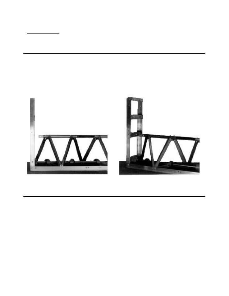
END FRAME ASSEMBLY
GENERAL
The end frames are symmetrical and can be used on either end. NOTE: The end frames for
the hydraulic drive are left hand and right hand.
1. Set an end frame on one of the screed
ends and align the two bottom holes
with the two holes in the edging. SeĆ
cure with two 3/8-16 X 1 whiz-lock
screws and two flange nuts (see Figure
21).
FIGURE 21
2. Attach eye bolt to clevis and place thru
hole in center of cross brace. Square
end frame with screed edging by adĆ
justing the two nuts on the eye-bolt
and then tightening them securely (see
Figure 22).
FIGURE 22
AIR DRIVE ASSEMBLY
1. Decided which end of screed the comĆ
bination regulator unit will be mounted.
2. Install 90 degree pipe fitting and nipple
on regulator end of air manifold. Install
pipe cap on opposite end of manifold.
3. Install end frames on either end of
screed, refer to End Frame Assembly.
4. On inlet side of regulator assembly
install pipe nipple and ball valve.
5. On outlet side of regulator assembly
install pipe nipple, 90 degree pipe fitĆ
ting and another pipe nipple.
6. Install pipe plug and pressure gage on
regulator assembly.
7. Install pipe rings on each side of air regĆ
ulator.
8. Using 3/8" bolts and nuts, mount air filĆ
ter assembly bracket to the screed end
bracket.
9. Using 5/16" bolts and nuts mount reguĆ
lator assembly to mounting bracket.
10.Install air hose between regulator asĆ
sembly outlet and screed air manifold.