Engine assembly, General – MBW Blitzscreed User Manual
Page 16
14
ENGINE ASSEMBLY
GENERAL
The engine can be put on any mechanical screed section on the left end where there are
bearings in two adjacent A-frames.
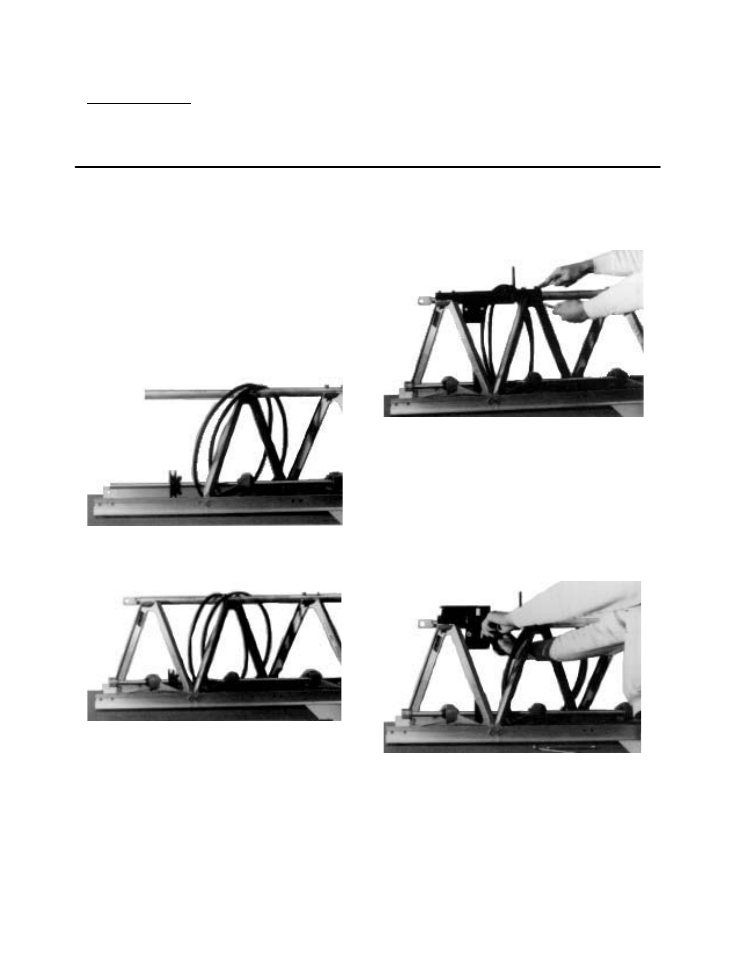
1. To install sheave, first remove left couĆ
pling driver. Support end of shaft when
driving out the spiral pin. Now remove
left end A-frame and clevis. Slide
#09126 sheave onto main shaft. Also
put both V-belts, supplied with engine
kit, around main shaft and over top of
the top tube (see Figure 13). ReassemĆ
ble left A-frame, clevis and coupling
driver (see Figure 14). Do not install the
top tube bolts at this time.
FIGURE 13
FIGURE 14
2. Remove the two top tube bolts from
right A-frame next to left A-frame reĆ
moved in Step 1. Set #09090 mounting
bracket on top tube and align holes up
over the two A-frames. Use four
3/8-16 X 2-1/2 bolts to secure mountĆ
ing bracket thru holes aligned above
(See Figure 15). These bolts replace
the original 3/8-16 X 2 bolts that were
removed earlier.
FIGURE 15
3. Place engine mounting deck (#09787)
on top of mounting bracket installed in
Step 2. Loosely install engine mountĆ
ing deck using four whiz-lock bolts
and flange nuts thru slots in mounting
deck and thru holes in mounting brackĆ
et (see Figure 16). The mounting deck
should be in its lowest position.
FIGURE 16
4. Bolt engine tight to the mounting deck
using four engine mounting bolts,
washers and flange nuts (see Figure
17).