General – MBW Blitzscreed User Manual
Page 13
11
SECTION ASSEMBLY
GENERAL
The following describes the assembly procedure of screed sections for both Mechanical
and Air Screeds. Most figures shown are of a Mechanical Screed. Section assembly of an
Air Screed is identical except where otherwise stated. It is essential to follow the proper
set-up sequence when assembling the screed for optimum performance.
IMPORTANT!
For steps 1-10, the screed sections
must be on a flat surface.
1. Determine the number of sections reĆ
quired to obtained the proper screed
length. Arrange the sections so the lonĆ
ger sections are in the middle and the
shorter sections are at the ends.
2. For the mechanical screed affix an enĆ
gine kit to one of the end sections or to
the middle section. Refer to Engine
Assembly for engine kit installation.
3. If an air screed is being used, refer to
Air Drive Assembly for instruction on
assembling air drive and end frames.
4. Assemble end frames and winches to
the end sections. Refer to End Frame
Assembly for installation of end
frames.
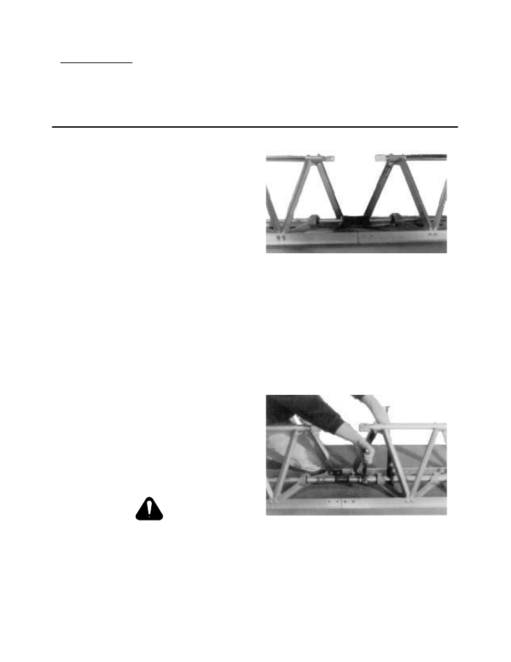
5. Start assembling sections at one end of
the screed. For mechanical screeds
place a flex coupling along with two flex
coupling collars between the two couĆ
pling drivers of adjoining sections. ColĆ
lars should be slid out to the ends of the
flex coupling (see Figure 2).
Check that the two vibrating shaft
offsets are in line.
IMPORTANT !
Assemble all sections in this manner.
Sight down top tubes of all sections
joined and straighten sections if necesĆ
sary.
FIGURE 2
For the air screed join the threaded
manifold ends with a manifold hose.
Use a pipe wrench to prevent the manĆ
ifold from turning while the hose ends
are tightened onto the manifold ends
(see Figure 3). Assemble all sections in
this manner. Sight down top tubes of all
sections joined and straighten sections
if necessary.
FIGURE 3
6. Install a two bolt splice plate thru float
edging. Install a four hole splice plate
on the outside of edging and loosely
install four blind nuts (see Figures 4 and
5).